Publicité
Liens rapides
FRANÇAIS
EV Charge Control
1. Consignes de sécurité
Les documents actuels peuvent être téléchargés à l'adresse phoenixcontact.net/products.
• L'installation, l'utilisation et la maintenance doivent être confiées à un personnel spécialisé dûment qualifié
en électrotechnique. Respecter les instructions d'installation. Lors de la mise en place et de l'exploitation des
stations de charge pour les véhicules électriques, respecter les dispositions et normes de sécurité en vigueur
(ainsi que les normes de sécurité nationales) de même que les règles générales relatives à la technique. Les
caractéristiques relatives à la sécurité se trouvent dans ces instructions et les certificats joints (attestation de
conformité, autres homologations éventuelles).
• L'ouverture ou la modification de l'appareil effectuée autrement que par la configuration est interdite. Ne pas
réparer l'appareil, mais le remplacer par un appareil équivalent. Seul le fabricant est autorisé à le réparer. Le
fabricant n'est pas responsable des dommages résultant d'infractions à cette règle.
• L'indice de protection IP20 (CEI 60529/EN 60529) de l'appareil est valable dans un environnement propre et
sec. Ne pas soumettre l'appareil à des sollicitations mécaniques et/ou thermiques dépassant les limites
décrites.
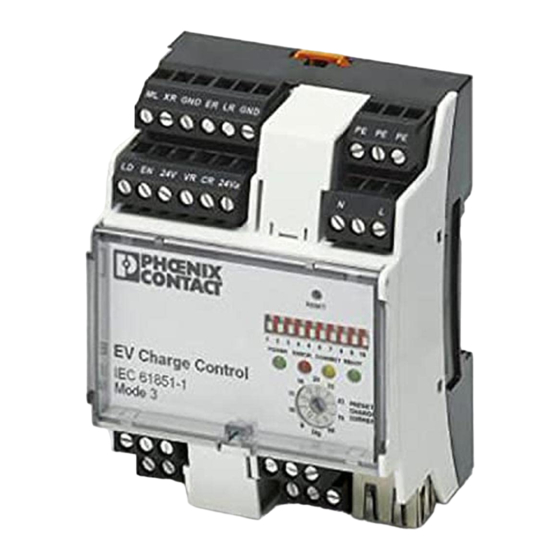
2. Brève description
Module Interface de commande et de surveillance lors du chargement des véhicules électriques. Le module
est équipé d'une interface de communication qui permet de lire voire d'écrire les données d'état ainsi que les
signaux de commande.
L'appareil est conçu pour charger les véhicules électriques en mode 3 conformément à la norme CEI 61851-
1 : chargement sur un équipement de charge défini à fonctions étendues ou, en option, de communication.
Selon son état, l'appareil permet d'activer/de désactiver le verrouillage du connecteur de charge de la station.
3. Eléments de commande et voyants
3.1 Bornes à vis ()
1
LD
Lock Detection
Entrée TOR accusé de réception de verrouillage,
activation via comm. de configuration 6
2
EN
Enable
Entrée TOR validation de chargement,
activation via comm. de configuration 7
3
24 V
Power
Sortie avec 24 V DC max. 100 mA
4
ML
Manual Lock
Entrée TOR verrouillage manuel,
activation via comm. de configuration 4 et 9
5
XR
External Release Entrée TOR état système F / disponibilité station de charge,
activation via comm. de configuration 8
6
GND
Masse
Terre du système, raccordée à la terre de protection
7
ER
Error
Sortie TOR activée lorsqu'une erreur apparaît
Erreur ou état E, ou alors état F
8
LR
Locking Request Sortie TOR activée tant que le verrouillage doit être actif
9
VR
Vehicle Ready
Sortie TOR, activée lorsque le véhicule est prêt
Etat C ou D
10
GND
Masse
Terre du système, raccordée à la terre de protection
11
CR
Charger Ready
Sortie TOR, activée lorsque la station de charge est opérationnelle
Etat B et PWM activé ; état C ou D
12
24 Va
Power
Entrée d'alimentation des sorties avec 7,5...30 V DC
13
A
RS-485
Raccordement d'énergie extérieure/appareils de mesure de puissance
14
B
RS-485
15
PE
Protective Earth
Terre de protection
16
N
Neutral
Conducteur neutre du réseau électrique
17
L
Line
Phase réseau électrique 110 V AC ... 240 V AC (L-N)
26
PX
Proximity
Signal de contrôle pour intensité maximale admise selon CEI 61851-1
27, 30,
R1-R3,
Retaining
Sortie de relais verrouillage,
29, 31
R2-R4
configuration via comm. de configuration 4 et 5
28
CP
ControlPilot
Signal interface, communication colonne de charge/véhicule
(CEI 61851-1)
32, 33 V1-V2
Ventilation
Sortie relais ventilateur : peut actionner un ventilateur lorsque l'état D est
atteint et que les entrées libérées et la mémoire sont activées.
34, 35 C1-C2 Contactor
Sortie relais contacteur : commute la tension secteur via un contacteur
extérieur du véhicule lorsque l'état C ou D est atteint et que les entrées
libérées et la mémoire sont activées.
3.2 Signalisations d'état et de diagnostic ()
20 Alimentation
vert
allumé
Tension d'alimentation existante
clignote (2 Hz)
Système en service
23 Error
rouge
allumé
Erreur (état E ou F)
22 Connect
jaune
allumé
Connecteur verrouillé
clignote (2 Hz)
Connecteur enfiché
21 Ready
vert
allumé
Charge du véhicule en cours
(contacteur entre secteur et véhicule activé)
clignote (2 Hz)
Véhicule opérationnel (état C ou D)
3.3 Sélecteurs de configuration ()
19 1
Requête PP
ON : requête PP, Case B, câble de charge et connecteur mâle sur
console de charge
OFF : pas de requête PP, Case C, câble de charge non amovible
19 2
Analyse PP
ON : refuser connecteur/câble à faible intensité maximale admise
OFF : admettre connecteur/câble à faible intensité maximale admise
19 3
Sélection PP
Utile uniquement lorsque 2 = ON
ON : refuser connecteur/câble 13 A
OFF : refuser connecteurs/câbles 13 A et 20 A
19 4
Verrouillage
ON : procéder au verrouillage
OFF : ne pas procéder au verrouillage
19 5
Option de verrouillage
Utile uniquement lorsque 4 = ON
(R4 sur 0 V,
ON : mécanisme de verrouillage option 1
R3 sur 24 V)
Moteur DC : le moteur de verrouillage est mis en service brièvement. Pour
verrouillage R1 sur 24 V (R2 demeure sur 0 V) et le déverrouillage R2
sur 24 V (R1 demeure sur 0 V)
OFF : mécanisme de verrouillage option 0
Electro-aimant : R1-R3 est excité (R1 sur 24 V) tant que le verrouillage
est requis, R2-R4 demeure en état initial pendant ce temps (R2 sur 0 V)
19 6
Accusé de réception
ON : analyser accusé de réception verrouillage de l'entrée LD
verrouillage
OFF : ne pas analyser accusé de réception verrouillage de l'entrée LD
19 7
Libération charge
ON : analyser libération charge entrée EN
OFF : ne pas analyser libération charge entrée EN
19 8
Disponibilité station de
ON : analyser disponibilité station de charge entrée XR
charge
OFF : ne pas analyser disponibilité station de charge entrée XR
19 9
Verrouillage manuel
ON : analyser verrouillage manuel entrée ML
OFF : ne pas analyser verrouillage manuel entrée ML
19 10 Libération via ETH (25)
ON : analyser bit de libération dans mémoire MODBUS
OFF : ne pas analyser bit de libération dans mémoire MODBUS
ENGLISH
EV charge control
1. Safety notes
You can download the latest documents at phoenixcontact.net/products.
• Installation, operation, and maintenance may only be carried out by qualified electricians. Follow the
installation instructions described. When installing and operating the charging station for electric vehicles,
the applicable regulations and safety directives (including national safety directives) as well as general
technical regulations, must be observed. The technical safety data is provided in this package slip and on the
certificates (conformity assessment, additional approvals where applicable).
• Changing or modifying the device beyond the configuration is not permitted. Do not repair the device
yourself; replace it with an equivalent device. Repairs may only be performed by the manufacturer. The
manufacturer is not liable for damage resulting from noncompliance.
• The IP20 protection (IEC 60529/EN 60529) of the device is intended for use in a clean and dry environment.
The device must not be subject to mechanical strain and/or thermal loads, which exceed the limits described.
2. Short description
Interface module for controller and monitoring functions during charging of electric vehicles. The module is
equipped with a communication interface, which allows status data and control signals to be read and written.
The device is designed for charging electric vehicles in mode 3 according to IEC 61851-1: charging at a defined
charging structure with extended and also optional communication functions.
The device can also activate/deactivate the charging plug lock depending on the state.
3. Operating and indicating elements
3.1 Screw terminal blocks ()
1
LD
Lock detection
Digital input for locking feedback,
activation via configuration switch 6
2
EN
Enable
Digital input for charge enable,
activation via configuration switch 7
3
24 V
Power
Output with 24 V DC max. 100 mA
4
ML
Manual lock
Digital input for manual locking,
activation via configuration switch 4 and 9
5
XR
External Release Digital input for system status F / charging station availability,
activation via configuration switch 8
6
GND
Ground
System grounding, connected to protective earth
7
ER
Error
Digital output is set when errors occur
Error or status E or status F
8
LR
Locking Request Digital output is set as long as locking is to remain active
9
VR
Vehicle Ready
Digital output is set when the vehicle is ready
Status C or D
10
GND
Ground
System grounding, connected to protective earth
11
CR
Charger Ready
Digital output is set when the charging station is ready
Status B and PWM switched on; status C or D
12
24 Va
Power
Supply input of outputs with 7.5 - 30 V DC
13
A
RS-485
Connection of external energy/power measurement devices
14
B
RS-485
15
PE
Protective Earth
Protective earth
16
N
Neutral
Neutral conductor, mains
17
L
Line
Mains phase 110 V AC ... 240 V AC (L-N)
26
PX
Proximity
Test signal for the current carrying capacity according to IEC 61851-1
27, 30,
R1-R3,
Retaining
Relay output lock, configuration via configuration switches 4 and 5
29, 31
R2-R4
28
CP
ControlPilot
Interface signal for communication charging station/vehicle
(IEC 61851-1)
32, 33 V1-V2
Ventilation
Ventilator relay output: switch on ventilator when status D is reached and
the enabled inputs and registers are active.
34, 35 C1-C2 Contactor
Contactor relay output: switch mains voltage to the vehicle via an external
contact when status C or D is reached and the enabled inputs and
registers are active.
3.2 Diagnostic and status indicators ()
20 Power
green
Lit
Supply voltage present
flashes (2 Hz)
System is running
23 Error
red
Lit
Error (status E or F)
22 Connect
yellow
Lit
Plug locked
flashes (2 Hz)
Plug inserted
21 Ready
green
Lit
Vehicle is charging
(contactor control between mains and vehicle)
flashes (2 Hz)
Vehicle ready (status C or D)
3.3 Configuration switch ()
19 1
PP request
ON: PP request, case B, charging cable with plug on the charger
OFF: no PP request, case C, charging cable firmly connected
19 2
PP evaluation
ON: reject plug with low current carrying capacity
ON: allow plug with low current carrying capacity
19 3
PP selection
Only relevant if 2 = ON
ON: Reject 13 A plug/cable
OFF: Reject 13 A and 20 A plug/cable
19 4
Lock
ON: execute locking
OFF: do not execute locking
19 5
Locking options
Only relevant if 4 = ON
(R4 to 0 V,
ON: locking mechanism option 1
(R3 to 24 V,
DC motor: the locking motor is switched on briefly. For locking R1 to
24 V (R2 remains at 0 V) and for locking R2 to 24 V (R1 remains at 0 V)
OFF: locking mechanism option 0
Lifting solenoid: R1-R3 is controlled as long (R1 to 24 V) as locking is
necessary, R2-R4 remains at basic status the whole time (R2 to 0 V)
19 6
Locking feedback
ON: evaluate locking feedback at input LD
OFF: do not evaluate locking feedback at input LD
19 7
Enable charging process ON: evaluate enable charging process input EN
OFF: do not evaluate enable charging process input EN
19 8
Charging station
ON: evaluate charging station availability input XR
availability
OFF: do not evaluate charging station availability input XR
19 9
Manual locking
ON: evaluate manual locking input ML
OFF: do not evaluate manual locking input ML
19 10 Enable via ETH (25)
ON: evaluate release bit in MODBUS register
OFF: do not evaluate release bit in MODBUS register
DEUTSCH
EV Charge Control
1. Sicherheitshinweise
Aktuelle Dokumente können unter der Adresse phoenixcontact.net/products heruntergeladen werden.
• Die Installation, Bedienung und Wartung ist von elektrotechnisch qualifiziertem Fachpersonal
durchzuführen. Befolgen Sie die beschriebenen Installationsanweisungen. Halten Sie die für das Errichten
und Betreiben von Ladestationen für Elektrofahrzeuge geltenden Bestimmungen und
Sicherheitsvorschriften (auch nationale Sicherheitsvorschriften), sowie die allgemeinen Regeln der Technik
ein. Die sicherheitstechnischen Daten sind dieser Packungsbeilage und den Zertifikaten
(Konformitätsbewertung, ggf. weitere Approbationen) zu entnehmen.
• Öffnen oder Verändern des Gerätes über die Konfiguration hinaus ist nicht zulässig. Reparieren Sie das
Gerät nicht selbst, sondern ersetzen Sie es durch ein gleichwertiges Gerät. Reparaturen dürfen nur vom
Hersteller vorgenommen werden. Der Hersteller haftet nicht für Schäden aus Zuwiderhandlung.
• Die Schutzart IP20 (IEC 60529/EN 60529) des Gerätes ist für eine saubere und trockene Umgebung
vorgesehen. Setzen Sie das Gerät keiner mechanischen und/oder thermischen Beanspruchung aus, die die
beschriebenen Grenzen überschreitet.
2. Kurzbeschreibung
Interface-Modul für Steuerungs- und Überwachungsfunktionen beim Laden von Elektrofahrzeugen. Das Modul
verfügt über eine Kommunikationsschnittstelle, über die Statusdaten sowie Steuersignale gelesen bzw.
geschrieben werden können.
Das Gerät ist für das Laden von Elektrofahrzeugen im Mode 3 gemäß der Norm IEC 61851-1 ausgelegt:
Aufladen an einer definierten Ladeinfrastruktur mit erweiterten, optional auch Kommunikationsfunktionen.
Mit dem Gerät kann zustandsabhängig die Verriegelung des Ladesteckers in der Ladestation aktiviert /
deaktiviert werden.
3. Bedien- und Anzeigeelemente
3.1 Schraubklemmen ()
1
LD
Lock Detection
Dig. Eingang Rückmeldung Verriegelung,
Aktivierung über Konfig.-Schalter 6
2
EN
Enable
Dig. Eingang Freigabe Ladevorgang,
Aktivierung über Konfig.-Schalter 7
3
24 V
Power
Ausgang mit 24 V DC max. 100 mA
4
ML
Manual Lock
Dig. Eingang Manuelle Verriegelung,
Aktivierung über Konfig.-Schalter 4 und 9
5
XR
External Release Dig. Eingang Systemstatus F / Verfügbarkeit Ladestation,
Aktivierung über Konfig.-Schalter 8
6
GND
Ground
Systemerde, verbunden mit der Schutzerde
7
ER
Error
Dig. Ausgang wird gesetzt, wenn Fehler auftreten
Fehler oder Status E oder Status F
8
LR
Locking Request Dig. Ausgang wird gesetzt, solange die Verriegelung aktiv sein soll
9
VR
Vehicle Ready
Dig. Ausgang wird gesetzt, wenn das Fahrzeug bereit ist
Status C oder D
10
GND
Ground
Systemerde, verbunden mit der Schutzerde
11
CR
Charger Ready
Dig. Ausgang wird gesetzt, wenn Ladestation bereit ist
Status B und PWM eingeschaltet; Status C oder D
12
24 Va
Power
Speiseeingang der Ausgänge mit 7,5...30 V DC
13
A
RS-485
Anschluss externer Energie-/Leistungsmessgeräte
14
B
RS-485
15
PE
Protective Earth
Schutzerde
16
N
Neutral
Neutralleiter Stromnetz
17
L
Line
Phase Stromnetz 110 V AC ... 240 V AC (L-N)
26
PX
Proximity
Prüfsignal für die Stromtragfähigkeit gemäß IEC 61851-1
27, 30,
R1-R3,
Retaining
Relaisausgang Verriegelung,
29, 31
R2-R4
Konfiguration über Konfig.-Schalter 4 und 5
28
CP
ControlPilot
Interfacesignal für Kommunikation Ladesäule/Fahrzeug (IEC 61851-1)
32, 33 V1-V2 Ventilation
Relaisausgang Ventilator: Ventilator einschalten, wenn Status D erreicht
ist und die freigegebenen Eingänge und Register aktiv sind
34, 35 C1-C2 Contactor
Relaisausgang Schütz: Netzspannung über ein externes Schütz auf das
Fahrzeug schalten, wenn Status C oder D erreicht ist und die
freigegebenen Eingänge und Register aktiv sind.
3.2 Diagnose- und Status-Anzeigen ()
20 Power
grün
leuchtet
Versorgungsspannung vorhanden
blinkt (2 Hz)
System läuft
23 Error
rot
leuchtet
Fehler (Zustand E oder F)
22 Connect
gelb
leuchtet
Stecker verriegelt
blinkt (2 Hz)
Stecker gesteckt
21 Ready
grün
leuchtet
Fahrzeug wird geladen
(Schütz zwischen Netz und Fahrzeug angesteuert)
blinkt (2 Hz)
Fahrzeug bereit (Zustand C oder D)
3.3 Konfigurationsschalter ()
19 1
PP-Abfrage
ON: PP-Abfrage, Case B, Ladekabel mit Stecker an der Ladekonsole
OFF: keine PP-Abfrage, Case C, Ladekabel fest angeschlossen
19 2
PP-Auswertung
ON: Stecker/Kabel mit geringer Stromtragfähigkeit abweisen
OFF: Stecker/Kabel mit geringer Stromtragfähigkeit zulassen
19 3
PP-Auswahl
Nur relevant, wenn 2 = ON
ON: 13 A Stecker/Kabel abweisen
OFF: 13 A und 20 A Stecker/Kabel abweisen
19 4
Verriegelung
ON: Verriegelung ausführen
OFF: Verriegelung nicht ausführen
19 5
Verriegelungsoption
Nur relevant, wenn 4 = ON
(R4 auf 0 V,
ON: Verriegelungsmechanismus Option 1
R3 auf 24 V)
DC-Motor: Der Verriegelungsmotor wird kurzzeitig eingeschaltet. Für die
Verriegelung R1 auf 24 V (R2 bleibt auf 0 V) und für die Entriegelung R2
auf 24 V (R1 bleibt auf 0 V)
OFF: Verriegelungsmechanismus Option 0
Hubmagnet: R1-R3 wird solange angesteuert (R1 auf 24 V), wie die
Verriegelung erforderlich ist, R2-R4 bleibt die ganze Zeit im
Grundzustand (R2 auf 0 V)
19 6
Verriegelung
ON: Rückmeldung Verriegelung an Eingang LD auswerten
Rückmeldung
OFF: Rückmeldung Verriegelung an Eingang LD nicht auswerten
19 7
Freigabe Ladevorgang
ON: Freigabe Ladevorgang Eingang EN auswerten
OFF: Freigabe Ladevorgang Eingang EN nicht auswerten
19 8
Verfügbarkeit Ladestation ON: Verfügbarkeit Ladestation Eingang XR auswerten
OFF: Verfügbarkeit Ladestation Eingang XR nicht auswerten
19 9
Manuelle Verriegelung
ON: Manuelle Verriegelung Eingang ML auswerten
OFF: Manuelle Verriegelung Eingang ML nicht auswerten
19 10 Freigabe über ETH (25)
ON: Freigabebit in MODBUS-Register auswerten
OFF: Freigabebit in MODBUS-Register nicht auswerten
PHOENIX CONTACT GmbH & Co. KG
Flachsmarktstraße 8, 32825 Blomberg, Germany
Fax +49-(0)5235-341200, Phone +49-(0)5235-300
phoenixcontact.com
MNR 9057647 - 02
DE
Einbauanweisung für den Elektroinstallateur
EN
Installation notes for electricians
FR
Instructions d'installation pour l'électricien
EM-CP-PP-ETH
4
5
6
7
8
9
10
11
12
13
14
15
3
16
ML
XR
GND
ER
LR
GND
A
B
PE
2
17
1
LD
EN
24V
VR
CR
24Va
N
L
18
19
RESET
20
1
2
3
4
5
6
7
8
9 10
POWER ERROR CONNECT READY
21
20
16
32
22
EV Charge Control
0
13
63
PRESET
CHARGE
23
IEC 61851-1
10
70
CURRENT
Mode 3
6
80
Dig
24
C2
V2
R2 R1
PX
35
25
C1
V1
R4 R3 CP
34
33
32
31
30
29 28
27
26
71,6
ML
XR
GND
ER
LR
GND
A
B
PE
LD
EN
24V
VR
CR
24Va
N
L
RESET
1
2
3
4
5
6
7
8
9 10
POWER ERROR CONNECT READY
20
EV Charge Control
16
0
32
13
63
PRESET
CHARGE
IEC 61851-1
10
70
CURRENT
Mode 3
6
Dig
80
C2
V2
R2 R1
PX
C1
V1
R4 R3 CP
N,L
b
ML
XR
GND
ER
LR
GND
A
B
PE
LD
EN
24V
VR
CR
24Va
N
L
RESET
ON
1
2
3
4
5
6
7
8
9 10
POWER ERROR CONNECT READY
20
16
32
EV Charge Control
0
1
10
13
63
PRESET
CHARGE
IEC 61851-1
10
70
CURRENT
Mode 3
6
Dig
80
C2
V2
R2 R1
PX
C1
V1
R4 R3 CP
230 V
L, L1-L3
N
PE
c
a
N,L
ML
XR
GND
ER
LR
GND
A
B
PE
LD
EN
24V
VR
CR
24Va
N
L
RESET
ON
1
2
3
4
5
6
7
8
9 10
POWER ERROR CONNECT READY
16
20
32
EV Charge Control
0
1
10
13
63
PRESET
CHARGE
IEC 61851-1
10
70
CURRENT
Mode 3
6
80
Dig
C2
V2
R2 R1
PX
C1
V1
R4 R3 CP
230 V
L, L1-L3
N
PE
c
a
© PHOENIX CONTACT 2014
PNR 104923 - 02
DNR 83126515 - 02
2014-04-04
2902802
61
50
44
55
OFF
OFF
Publicité

Manuels Connexes pour Phoenix Contact EM-CP-PP-ETH


Sommaire des Matières pour Phoenix Contact EM-CP-PP-ETH
- Page 1 PHOENIX CONTACT GmbH & Co. KG FRANÇAIS ENGLISH DEUTSCH Flachsmarktstraße 8, 32825 Blomberg, Germany EV Charge Control EV charge control EV Charge Control Fax +49-(0)5235-341200, Phone +49-(0)5235-300 phoenixcontact.com MNR 9057647 - 02 2014-04-04 1. Consignes de sécurité 1. Safety notes 1.
- Page 2 Humidité de l'air pas de condensation Humidity non-condensing Luftfeuchtigkeit keine Betauung 30 ... 95 % Conformité / Homologations Conformité CE Conformance / approvals CE-compliant Konformität / Zulassungen CE-konform © PHOENIX CONTACT 2014 PNR 104923 - 02 DNR 83126515 - 02...
- Page 3 PHOENIX CONTACT GmbH & Co. KG ESPAÑOL PORTUGUÊSE ITALIANO Flachsmarktstraße 8, 32825 Blomberg, Germany EV Charge Control EV Charge Control EV Charge Control Fax +49-(0)5235-341200, Phone +49-(0)5235-300 phoenixcontact.com MNR 9057647 - 02 2014-04-04 1. Advertencias de seguridad 1. Instruções de segurança 1.
- Page 4 Humedad del aire sin condensación Umidade do ar sem condensação Umidità senza condensa 30 ... 95 % Conformidad / Homologaciones Conformidad CE Conformidade / Certificações Conforme CE Conformità/omologazioni CE conforme © PHOENIX CONTACT 2014 PNR 104923 - 02 DNR 83126515 - 02...
- Page 5 中文 PHOENIX CONTACT GmbH & Co. KG РУССКИЙ TÜRKÇE Flachsmarktstraße 8, 32825 Blomberg, Germany EV 充电控制器 Зарядное устройство для электромобилей EV Charge Control EV şarj kontrolü Fax +49-(0)5235-341200, Phone +49-(0)5235-300 phoenixcontact.com MNR 9057647 - 02 2014-04-04 1. 安全提示 1. Правила техники безопасности...
- Page 6 0,2 ... 4 mm² / 0,2 ... 2,5 mm² / 24 - 12 湿度 无冷凝 Отн. влажность воздуха без выпадения конденсата yoğunlaşma yok 30 ... 95 % © PHOENIX CONTACT 2014 PNR 104923 - 02 DNR 83126515 - 02 符合性/认证 符合 CE 标准 Соответствие нормам /допуски Соответствие CE...