Leviton decora PR180 Manuel D'installation
Liens rapides
WARNINGS AND CAUTIONS:
• To be installed and/or used in accordance with appropriate electrical codes and regulations.
• If you are not sure about any part of these instructions, consult a qualified electrician.
• To avoid overheating and possible damage to this device and other equipment, do not install to control a receptacle, a motor, or a transformer-operated appliance other than applicable fluorescent lighting.
• Use this device only with copper or copper clad wire. With aluminum wire use only devices marked co/alr or cu/al.
• Clean outer surface gently with damp cloth only. DO NOT use soaps or cleaning liquids.
• No user serviceable components. DO NOT attempt to service or repair.
DESCRIPTION
The Decora 3-Way Wide-View Motion Activated Light Control, Leviton Cat. No. PR180, is a passive infrared motion sensor switch designed to offer energy management capabilities to the end-user. Cat. No. PR180 operates by detecting
motion (such as body heat) within its field-of-view (area of coverage) and automatically switches lights ON. When motion is no longer detected, lights remain ON for a selected time and automatically switch OFF. Cat. No. PR180 is suitable
for indoor use only. Energy is saved with this motion switch and is ideal for any room in your home that would benefit from automatic "hands-free" light control, such as in bathrooms, bedrooms, and living areas.
Cat. No. PR180 is equipped with sensitivity and time adjustment controls, which enable the user to control the light and time settings. See "ADJUSTMENT SETTINGS" section.
FEATURES
• Cat. No. PR180 has a sensing area of coverage of 20 ft. x 20 ft., and a sensing angle of 180
• Adjustable light and time-delay controls are located on the front of the device (Figure 2).
• Manual override permits normal ON/OFF operation.
• LED indicator light is OFF when the switch is in automatic (AUTO) mode and flashes when motion is detected.
SPECIFICATIONS
• Not intended for use with electronic ballasts.
• Jumper wires required for 3-way use.
• Intended for use with rapid start fluorescent or incandescent lighting only.
• Installing this device requires experience with residential and commercial wiring practices. Consult local building
codes before attempting to install this device.
LOCATION / MOUNTING
Since Cat. No. PR180 responds to temperature changes, care should be taken when mounting the device. DO NOT
mount directly above a heat source, in a location where hot or cold drafts will blow directly on the sensor, or where
unintended motion (e.g., hallway traffic) will be within sensor's field-of-view.
TO INSTALL
WARNING:
1.
TO AVOID FIRE, SHOCK, OR DEATH; TURN OFF POWER AT CIRCUIT BREAKER OR FUSE AND TEST
THAT THE POWER IS OFF BEFORE WIRING!
FOR SINGLE POLE INSTALLATION:
2A.
A. Connect lead wires per WIRING DIAGRAM as follows: Black lead to Line (HOT), Red lead to Load wire, Green lead to
ground. Remaining Yellow/Red lead should have Red insulation label affixed. This lead will not be used.
NOTE: If insulating label is not affixed to Yellow/Red lead, use a small wire nut or electrical tape to cap off.
B. Twist strands of each lead tightly, and with circuit conductors, push firmly into appropriate wire connector. Screw
connectors on clockwise ensureing that no bare conductor shows below the wire connectors. Secure each connector with
electrical tape.
FOR 3-WAY INSTALLATION:
2B.
NOTE: On Switch #1 (the 3-way switch that is to remain), two jumper wires are required between the common terminal
(usually a Black screw) and one of the switch wire terminals to supply power to Cat. No. PR180 (to be installed later in this
installation) regardless of the ON/OFF position of Switch #1.
NOTE: If you are UNSURE which wires are common, FOLLOW STEPS A-G. You will need either a test lamp, neon circuit
tester, or a voltmeter.
CAUTION:
TAKE ExTREME CARE AS YOU WILL BE WORKING WITH LIVE CONDUCTORS.
A. TURN OFF POWER. Disconnect all wires from both 3-Way switches and leave them outside the wall box ensuring that
they are not touching each other. Temporarily connect one lead from your tester to a known Ground (such as a wall box
or its Ground wire). If none are available, connect to a structural Ground, such as a water pipe.
B. RESTORE POWER. Only one of the six, non-Grounding wires should be "Hot". Using the tester, find it and label it "Line
Hot". Mark its wall box "Line". The other two wires are travellers, mark them "A" and "B".
C. TURN OFF POWER. Temporarily connect "A" to "Line Hot".
D. RESTORE POWER and go to the other wall box. Only one wire there will be "Hot" Using the tester, find it and label it "A".
E. TURN OFF POWER. At the "Line" wall box, disconnect "A" and "Line Hot" and temporarily connect "B" and "Line Hot".
F. RESTORE POWER. At the second wall box, only one wire should be "Hot". Using the tester, find it and label it "B". Label
the last, non-Grounding wire at the wall box "Load Hot".
G. TURN OFF POWER. Disconnect "B" and "Line Hot". Proceed with installation.
3.
Replace wires from the common terminal and one switch terminal with short jumpers. Connect two jumpers "Line Hot" and
"Traveler A" (see steps A-G if necessary) together with wire connector. Screw connector on clockwise. Secure connector
with electrical tape.
Connect wires per WIRING DIAGRAM as follows: Red lead to Load. Traveler "A" to Black. Traveler "B" to Yellow/Red.
4.
NOTE: If wire nut is provided, use to join one 14 AWG supply conductor with one 16 or 18 AWG device control lead.
5.
Reinstall Switch #1 and RESTORE POWER.
6.
With Cat. No. PR180 in the ON position, toggle Switch #1 and follow steps in chart.
7.
TURN OFF POWER.
8.
Gently position wires to provide room in the wall box for switch.
9.
Mount device "TOP" up.
10. Restore power at circuit breaker or fuse.
ADJUSTMENT SETTINGS
1. With power restored and wallplate removed, use your finger or a small screwdriver to adjust the light sensitivity
and time settings on the device as follows:
Light Level Adjustment:
• Turn the control towards the "+" sign. Lights will turn ON in lighter conditions.
• Turn the control towards the "-" sign. Lights will turn ON in less lighting conditions.
Time Selection:
• Adjust the time selector to the desired length of time the lights are to remain ON. Lights will remain ON from
15 seconds to 15 minutes after the room is vacated.
• Turn the control towards the "+" sign. Lights will remain ON up to 15 minutes.
• Turn the control towards the "-" sign. Lights will remain ON up to 15 seconds.
2. Test that the light level and time selection are as desired. If not, repeat adjustments until satisfied.
3. Mount wallplate. INSTALLATION IS COMPLETE.
TO OPERATE
Cat. No. PR180 operates in three modes:
ON:
Slide switch to the far RIGHT.
OFF:
Slide switch to the far LEFT.
Switch is at CENTER position.
AUTO:
NOTES:
• Allow 1 minute for Cat. No. PR180 to warm-up before using in auto mode.
• In AUTO mode the device will switch lights OFF in an occupied room if no motion is detected for the selected time
delay. If continuous operation is desired, select the ON position.
TROUBLESHOOTING
Lights do not switch ON when motion is detected:
• Push switch to AUTO. LED should flash when motion is detected.
• Motion is beyond sensing range, move closer to switch.
• Adjust the light level adjustment toward lighter or darker, depending on room conditions.
Lights always stay ON:
• Check that switch is in AUTO position.
• Be sure that no motion occurs in coverage area for time selected.
• Check that switch is not installed near a heat source (e.g., stove, lights, heat vents) or detecting motion from an
adjacent area (e.g., hallway traffic). If so, switch may have to be relocated.
Lights do not turn ON in AUTO or MANUAL ON modes:
• Check that switch is installed correctly.
• Check that power is ON.
• Check that light bulb is functioning.
• If applicable, check that switch on controlled unit is ON.
NOTE: If problems continue, consult a qualified electrician.
Leviton warrants to the original consumer purchaser and not for the benefit of anyone else that this product at the time of its sale by Leviton is free of defects in materials and workmanship under normal and proper use for five years from the purchase date. Leviton's
only obligation is to correct such defects by repair or replacement, at its option, if within such five year period the product is returned prepaid, with proof of purchase date, and a description of the problem to Leviton Mfg. Co., Inc. 201 North Service Road, Melville,
N.Y. 11747, U.S.A. This warranty excludes and there is disclaimed liability for labor for removal of this product or reinstallation. This warranty is void if this product is installed improperly or in an improper environment, overloaded, misused, opened, abused, or altered in
any manner, or is not used under normal operating conditions or not in accordance with any labels or instructions. There are no other or implied warranties of any kind, including merchantability and fitness for a particular purpose, but if any implied warranty is
required by the applicable jurisdiction, the duration of any such implied warranty, including merchantability and fitness for a particular purpose, is limited to five years. Leviton is not liable for incidental, indirect, special, or consequential damages, including without
limitation, damage to, or loss of use of, any equipment, lost sales or profits or delay or failure to perform this warranty obligation. The remedies provided herein are the exclusive remedies under this warranty, whether based on contract, tort or otherwise.
Single Pole and 3-Way Wide View Motion Activated Light Control
Cat. No. PR180
Ratings: 500W-120VAC, 60Hz (Incandescent)
400VA-120VAC, 60Hz (Fluorescent - MAGNETIC RAPID START BALLASTS ONLY)
INDOOR USE ONLY
INSTALLATION
(Figure 1).
O
LIMITED 5 YEAR WARRANTY AND EXCLUSIONS
For Technical Assistance Call: 1-800-824-3005 (U.S.A. Only)
www.leviton.com
FIGURE 1
180°
20'
15'
10'
5'
SWITCH
INTERRUPTEUR-DETECTEUR / InterrUPtOr
10'
10'
3 m
3 m
0
3-WAY INSTALLATION / INSTALLATIONS à TROIS VOIES / Para InstalacIón de tres Vías
STEP A
If light
TURN OFF POWER
Restest.
Go to
does not
and reverse Red
steps
turn ON.
and Black wires on
Cat. No. PR180.
B or C.
RESTORE POWER.
Set sensor to AUTO. If switch #1 can turn lights ON, then wiring is correct. Proceed with
If light turns ON
instructions step 9.
when Switch #1 is
If Switch #1 (with jumper) can not turn lights ON, TURN OFF POWER and reverse Black and
either position.
Yellow wires on PR180. RESTORE POWER and retest.
ÉTAPE A
Si le
COUPER LE
luminaire
COURANT et inverser
ne s'allume
les fils rouge et noir
du PR180. RÉTABLIR
pas,
LE COURANT.
Si le luminaire
Mettre le PR180 en mode automatique; si l'autre interrupteur peut allumer le luminaire, alors
s'allume quelle que
les dispositifs sont bien raccordés. Passer à l'étape 9.
soit la position de la
Si le premier interrupteur (avec cavaliers) n'allume pas le luminaire, COUPER LE COURANT
bascule du premier
et inverser les fils noir et jaune du PR180. RÉTABLIR LE COURANT et vérifier de nouveau.
interrupteur,
PASO A
Si las
INTERRUMPA LA
Haga otra
prueba.
luces
CORRIENTE e
invierta los alambres
Vaya a los
no se
encienden
Rojo y Negro en
pasos B
el No.Cat. PR180.
o C.
RESTABLEZCA LA
CORRIENTE.
Si las luces se
Fije el sensor en AUTO. Si el interruptor #1 enciende las luces, entonces el cableado está
ENCIENDEN
correcto. Proceda con las instrucciones en el paso 9.
cuando el interruptor
Si el interruptor #1 (con empalme) no enciende las luces, INTERRUMPA LA CORRIENTE
#1 está en cualquier
e invierta los alambres Negro y Amarillo en el Cat. No. PR180. RESTABLEZCA LA
posición.
CORRIENTE y haga otra prueba.
Wiring Diagram 1 – Single Pole Installation
Schéma de cåblage 1 – Installations Unipolaires
Diagrama de Cableado 1 – Para Instalación Unipolar
Hot (Black) / Actif (Noir) / Fase (Negro)
Yellow/Red
Jaune/Rouge
Amarillo/Rojo
Line 120VAC, 60 Hz
Ligne 120 V c.a., 60 Hz
Línea 120VCA, 60 Hz
NOTE: This wire is unused during single pole installations. Cover exposed wire with electrical tape or small wire cap.
REMARQUE : ce fil n'est pas utilisé dans les installations unipolaires. Recouvrir les fils exposés d'une marette et de ruban isolant.
NOTA: Este conductor no se usa en una instalación unipolar. Cubra el conductor expuesto con cinta aislante o un conector pequeño.
Neutral (White) / Neutre (Blanc) / Neutro (Blanco)
Wiring Diagram 2 – 3-Way Installation
Schéma de cåblage 2 – Installations à Trois Voies
Diagrama de Cableado 2 – Para Instalación de Tres Vías
Switch #1
Hot (Black)
Actif (Noir)
Fase (Negro)
Traveler A
Cavalier A / Viajero A
Line 120VAC, 60 Hz
Green Ground
Ligne 120 V c.a., 60 Hz
Terre Vert
Línea 120VCA, 60 Hz
Verde a tierra
Traveler B / Cavalier B / Viajero B
Neutral (White) / Neutre (Blanc) / Neutro (Blanco)
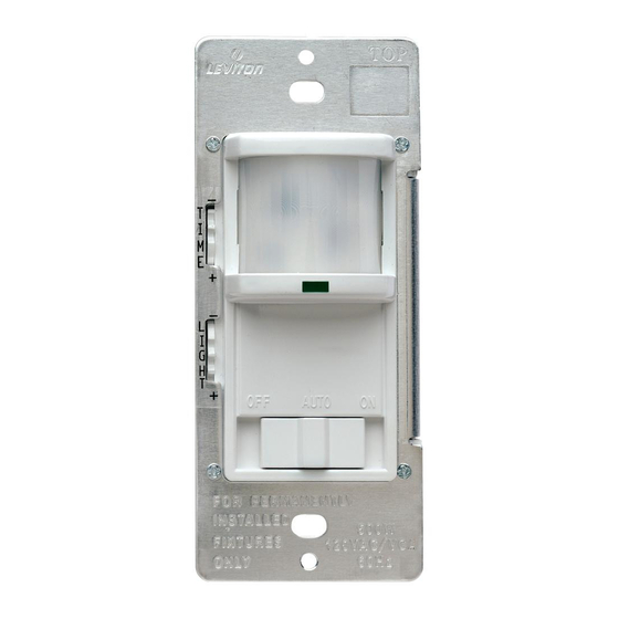
FIGURE 2
TOP
6,1 m
(2) Control Settings
(Time and Lights)
5 m
2 réglages
–
(délai d'eteinte et
T
I
éclairage ambiant)
M
3 m
E
(2) Programadores
+
de control
1,5 m
(tiempo y luz)
–
L
I
G
H
(3) Operation Modes
T
+
(Auto, OFF and ON)
(3) modes de fonctionnement
("Auto", "OFF" et "ON")
OFF
AUTO
(3) Modos de Operación
(auto, apagado y encendido)
STEP B
If light turns ON only
TURN OFF POWER
when Switch #1 is
and reverse Red
and Yellow wires
in either the UP or
on Cat. No. PR180.
DOWN position.
RESTORE POWER.
STEP C
ÉTAPE B
Vérifier de
COUPER LE
Si le luminaire ne
nouveau
s'allume que lorsque
COURANT et inverser
et Passer
le premier interrupteur
les fils rouge et jaune
à l'étape B
du PR180. RÉTABLIR
est soit SOUS ou
ou C.
LE COURANT.
HORS TENSION.
ÉTAPE C
PASO B
Si las luces se
INTERRUMPA LA
CORRIENTE e
ENCIENDEN sólo
invierta los alambres
cuando el interruptor
#1 está en la posición
Rojo y Amarillo en
de ARRIBA o ABAJO.
el No. Cat. PR180.
RESTABLEZCA LA
CORRIENTE.
PASO C
PR180
Black / Noir / Negro
Red / Rouge / Rojo
Green Ground
Terre Vert
Verde a tierra
PR180
Common Terminal (Black Screw)
Borne commune (vis noir)
Terminal Común (Tornillo Negro)
Jumper / Cavalier / Puente
Red / Rouge / Rojo
Black / Noir / Negro
Yellow/Red
Jaune/Rouge
Amarillo/Rojo
Green Ground
Terre Vert
Verde a tierra
DI-000-PR180-22C-x0
ENGLISH
Sensor
Détecteur
Sensor
LED
Témoin
led
Slide Switch
Bascule
Interruptor
ON
deslizante
Retest.
Go to
steps
A or C.
Vérifier de
nouveau
et passer
à l'étape A
ou C.
Haga otra
prueba.
Vaya a los
pasos
A o C.
Black
Noir
Negro
LOAD
Charge
Carga
White
Blanc
Blanco
Black
Noir
Negro
LOAD
Charge
Carga
White
Blanc
Blanco

Manuels Connexes pour Leviton decora PR180


Sommaire des Matières pour Leviton decora PR180
- Page 1 There are no other or implied warranties of any kind, including merchantability and fitness for a particular purpose, but if any implied warranty is required by the applicable jurisdiction, the duration of any such implied warranty, including merchantability and fitness for a particular purpose, is limited to five years. Leviton is not liable for incidental, indirect, special, or consequential damages, including without limitation, damage to, or loss of use of, any equipment, lost sales or profits or delay or failure to perform this warranty obligation.
- Page 2 Leviton, et n’en présentera pas tant qu’il est utilisé de façon normale et adéquate, pendant une période de 5 ans suivant la date d’achat. La seule obligation de Leviton sera de corriger les dits défauts en réparant ou en Leviton garantiza al consumidor original de sus productos y no para beneficio de nadie más que este producto en el momento de su...