Publicité
Liens rapides
HARTING Electronics GmbH
P.O. Box 14 73 | D-32339 Espelkamp
HARTING.electronics@HARTING.com
Hybrid Metall Steckverbinder · Hybrid Metal Connector
Connecteur métallique hybride
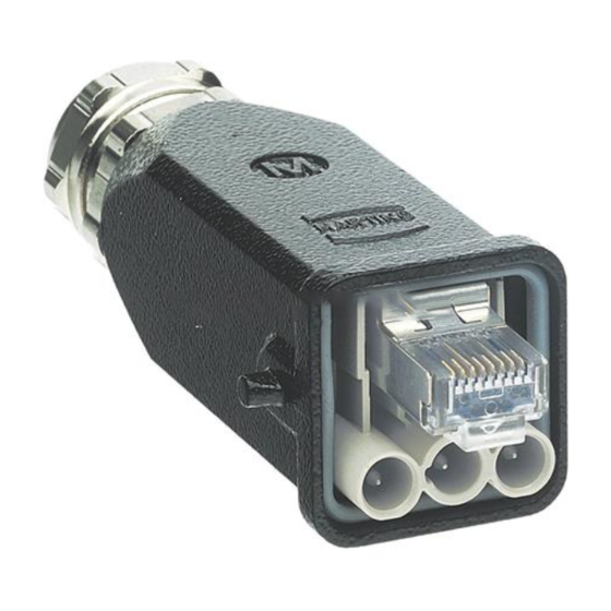
HARTING Han® 3 A Hybrid RJ45
Bestell-Nummern · Part numbers · Réf. articles
09 57 308 0500 000 · 09 57 308 0501 000
www.HARTING.com
Inhalt · Content · Contenu
Han® 3 A
Kabelführung
Hybrid RJ45
Plastik
Geräteseite
Plastic wire
Han® 3 A
manager
Hybrid RJ45
Passage de
Device side
câble plastique
Han® 3 A
Hybrid RJ45
Côté appareil
Kabel-
Kabelführung
verschraubung
Metall
Cable gland
Metal wire
manager
Passe-câble
Passage de
câble métal
Tüllengehäuse
Einsatz ohne
mit Dichtung
Rasthebel
Hood with
Insert without
sealing
locking lever
Boîtier avec
Insert sans
joint
levier de
blocage
Dichtschraube
Schirmblech
M3
unten
Sealing screw
Bottom shell
M3
Elément de
Vis d'étanchéité
blindage
M3
inférieur
Isolierkörper
Schirmblech
oben
Insulator
Top shell
Elément isolant
Elément de
blindage
supérieur
Montageanleitung · Assembly instruction
Deutsch
Instructions d'assemblage
E
NGLISH
Français
1. Vorbereitung des Hybridkabels: Das Kabel wie folgt abisolieren
und zuschneiden.
Preparation of the hybrid cable: Strip and cut the wires as
follows.
Préparation du câble hybride: Dénuder le câble comme indiqué ci-
après et couper.
2. Crimpung der Han D® Kontakte, kabel- und geräteseitig: Crimp-
werkzeug 09 99 000 0001 verwenden um die Han D® Kontakte zu
crimpen. Abisolierlänge 6 mm. Der Han D® Kontakt mit der Ver-
schraubung ist die GND / PE Anbindung, die nach der Montage direk-
ten Kontakt mit dem Gehäuse hat.
Crimping of the Han D® contacts, cable and device side: Use
crimping tool 09 99 000 0001 and a stripping length of 6 mm
to crimp the power wires to the Han D® contacts. The Han D®
contact with thread is the GND / PE one and has direct contact
to the housing after assembly.
Sertissage des contacts Han D®, côté câble et côté appareil: Utili-
ser l'outil de sertissage 09 99 000 0001 afi n de sertir les contacts Han
D®. Longueur de dénudage 6 mm. Le contact Han D® avec raccord vis-
sé est la liaison GND / PE qui, après le montage, est en contact directe
avec le boîtier.
3. Montage
des
RJ45
Datenmoduls:
09 45 800 0520 verwenden um den Datenmanager mit den verdrillten
Litzen zu verbinden. Die überstehenden Litzenenden direkt vor dem Da-
tenmanager abschneiden. Anschluss gemäß EIA TIA 568B. Den Daten-
manager in den Isolierkörper einfügen und das obere- bzw. das untere
Schirmblech aufsetzen und einrasten.
Assembly of the RJ45 data module: Use crimping tool
09 45 800 0520 to connect the data manager to the twisted pair
wires. Cut the protruding wires directly in front of the data
manager, loading plan according to EIA TIA 568B. Insert the data
manager to the plastic body and clip top and bottom shells onto
the insert.
Montage du module de données RJ45: Utiliser l'outil de sertissage
09 45 800 0520 afi n de relier le gestionnaire de données aux brins to-
ronnés. Couper les extrémités du fi l toronné juste avant le gestionnaire
de données. Raccordement selon EIA TIA 568B. Insérer le gestionnaire
de données dans l'élément isolant et placer l'élément de blindage su-
périeur ou inférieur puis enclipser.
Schirmblech oben
Top shell
Elément de blindage inférieur
Schirmblech unten · Bottom shell · Elément de blindage supérieur
4. Montage der Kabelseite: Die Han D® Kontakte in den Isolierkörper
einrasten und das RJ45 Datenmodul einführen.
Assembly of the cable side: Clip the Han D® contacts into the
isolation body and insert the RJ45 data module.
Montage côté câble: Enclipser les contacts Han D® dans l'élément
isolant et insérer le module de données RJ45.
Das
Crimpwerkzeug
Publicité

Manuels Connexes pour HARTING Han 3 A Hybrid RJ45

Sommaire des Matières pour HARTING Han 3 A Hybrid RJ45
- Page 1 09 45 800 0520 to connect the data manager to the twisted pair Préparation du câble hybride: Dénuder le câble comme indiqué ci- HARTING Han® 3 A Hybrid RJ45 wires. Cut the protruding wires directly in front of the data après et couper.
- Page 2 5. Montage der Geräteseite und Abmessungen des Gehäuseaus- Technische Daten schnitts: Die Han D® Kontakte in den Isolierkörper einrasten. Ab- Technical Characteristics schließend in die Han® 3 A Buchse einschieben und die Schraube mit Caractéristiques techniques 0,5 Nm festziehen. Assembly of the device side and panel cut out dimensions: Clip Schutzart: the Han D®...