Publicité

Les langues disponibles
  • FR

Les langues disponibles

  • FRANÇAIS, page 46

Liens rapides

Betriebsanleitung
Heizkreisverteiler
Version: 08.2020.0
ID: 900.000.0497
Copyright 2020 AFRISO-EURO-INDEX GmbH. Alle Rechte vorbehalten.
ProCalida®
Typ: EF1
Lindenstraße 20
74363 Güglingen
Telefon +49 7135 102-0
Service +49 7135 102-211
Telefax +49 7135 102-147
info@afriso.com
www.afriso.com

Publicité

Table des Matières
loading

Sommaire des Matières pour afriso ProCalida EF1

  • Page 1 Betriebsanleitung Heizkreisverteiler ProCalida® Typ: EF1 Copyright 2020 AFRISO-EURO-INDEX GmbH. Alle Rechte vorbehalten. Lindenstraße 20 74363 Güglingen Telefon +49 7135 102-0 Service +49 7135 102-211 Telefax +49 7135 102-147 info@afriso.com www.afriso.com Version: 08.2020.0 ID: 900.000.0497...
  • Page 2 Über diese Betriebsanleitung Über diese Betriebsanleitung Diese Betriebsanleitung beschreibt den Heizkreisverteiler „ProCalida® EF 1“ (im Folgenden auch „Produkt“). Diese Betriebsanleitung ist Teil des Pro- dukts. • Sie dürfen das Produkt erst benutzen, wenn Sie die Betriebsanleitung vollständig gelesen und verstanden haben. •...
  • Page 3 Informationen zur Sicherheit Informationen zur Sicherheit Warnhinweise und Gefahrenklassen In dieser Betriebsanleitung finden Sie Warnhinweise, die auf potenzielle Gefahren und Risiken aufmerksam machen. Zusätzlich zu den Anweisungen in dieser Betriebsanleitung müssen Sie alle am Einsatzort des Produktes gel- tenden Bestimmungen, Normen und Sicherheitsvorschriften beachten. Stel- len Sie vor Verwendung des Produktes sicher, dass Ihnen alle Bestimmun- gen, Normen und Sicherheitsvorschriften bekannt sind und dass sie befolgt werden.
  • Page 4: Informationen Zur Sicherheit

    Informationen zur Sicherheit Bestimmungsgemäße Verwendung Dieses Produkt eignet sich ausschließlich zum Verteilen von Medien in Flä- chenheizungs- und Kühlsystemen in Gebäuden bei Verwendung folgender Medien: • Heizwasser nach VDI 2035 • Wasser-Glykol-Gemische mit max. 50% Beimischung Eine andere Verwendung ist nicht bestimmungsgemäß und verursacht Gefahren.
  • Page 5 Informationen zur Sicherheit Vorhersehbare Fehlanwendung Das Produkt darf insbesondere in folgenden Fällen und für folgende Zwecke nicht angewendet werden: • Verteilung von Trinkwasser Qualifikation des Personals Arbeiten an und mit diesem Produkt dürfen nur von Fachkräften vorgenom- men werden, die den Inhalt dieser Betriebsanleitung und alle zum Produkt gehörenden Unterlagen kennen und verstehen.
  • Page 6: Transport Und Lagerung

    Transport und Lagerung Transport und Lagerung Das Produkt kann durch unsachgemäßen Transport und Lagerung beschä- digt werden. HINWEIS UNSACHGEMÄSSE HANDHABUNG • Stellen Sie sicher, dass während des Transports und der Lagerung des Pro- dukts die spezifizierten Umgebungsbedingungen eingehalten werden. • Benutzen Sie für den Transport die Originalverpackung.
  • Page 7 Produktbeschreibung Produktbeschreibung Die Heizkreise bestehen aus einem Vor- und einem Rücklauf. Übersicht Standardausführung Zubehör (optional) A. Rücklaufventil 1. Kugelhahn G1 B. Verteilerstrang (Varianten 2. Anschlusswinkel abhängig) 3. Schnellentlüfter C. Durchflussmesser 4. Distanzstück 60 mm D. Endkappe 5. Stellantrieb E. Entlüftungsventil 6.
  • Page 8 Produktbeschreibung Abmessungen und Anschlüsse Heizkreise 2 Abstand A 79 129 129 129 129 179 179 179 229 229 229 Abstand B 100 100 100 150 200 200 200 250 250 300 300 Abstand C 76 126 126 126 126 176 176 176 176 226 Abstand D 23 123 123 123 123 173 Abstand E 34...
  • Page 9 Produktbeschreibung 30 mm 46 mm 79 mm ProCalida® EF 1...
  • Page 10 Produktbeschreibung Funktion Das Produkt verteilt das Medium in den Rohrleitungsschleifen. Technische Daten Parameter Wert Allgemeine Daten Hauptanschluss G1 mit Überwurfmutter G1 Außengewinde Heizkreisanschluss Eurokonus Betriebstemperatur und -druck Max. 60 °C bei 6 bar Max. 90 °C bei 3 bar Verteilerdurchfluss Max.
  • Page 11: Montage

    Montage Montage Das Produkt wird in einem Verteilerschrank, Auf- oder Unterputz, an der Wand montiert.  Stellen Sie sicher, dass die Anlage drucklos ist. WARNUNG HEISSE FLÜSSIGKEIT Medien in Heizungsanlagen stehen unter einem hohen Druck und können Tem- peraturen bis über 100 °C erreichen. •...
  • Page 12 Montage  Stellen Sie sicher, dass der obere Verteiler A leicht schräg befestigt ist und Verteiler B gerade. 2. Klappen Sie den Bügel nach oben und rasten Sie ihn ein (klick). 3. Fixieren Sie den Bügel mit einer Schraube. ProCalida® EF 1...
  • Page 13 Montage Überströmventil einbauen Beim Einbau eines Überströmventils kann die Anlage nicht mehr an den End- kappen befüllt und gespült werden. HINWEIS UNSACHGEMÄSSE HANDHABUNG • Stellen Sie sicher, dass die KFE-Hähne eingebaut sind, bevor Sie die Anlage befüllen oder spülen. Nichtbeachtung dieser Anweisungen kann zu Sachschäden führen. 1.
  • Page 14 Montage 2. Ersetzten Sie die Spindel durch die Verschluss- schraube (D). Wenn eine Endkappe eingebaut ist: Ersetzen Sie die Endkappe (E) durch eine Endkappe mit Schlauchanschluss (F). ProCalida® EF 1...
  • Page 15 Montage 3. Bauen Sie das Über- strömventil ein. 4. Achten Sie auf die Durch- flussrichtung (G). 5. Stellen Sie den Druck am Überströmventil (H) ein. - Stufenlos einstellbar 0,1 bar - 0,5 bar. ProCalida® EF 1...
  • Page 16 Montage p: Differenzdruck [mbar] Q: Volumenstrom [l/h] Abbildung 1: Diagramm Differenzdruck am Überströmventil ProCalida® EF 1...
  • Page 17: Produkt In Betrieb Nehmen

    Inbetriebnahme Inbetriebnahme Produkt in Betrieb nehmen 1. Schließen Sie den Schlauch (D) an der Endkappe mit dem Schlauchanschluss oder am KFE-Hahn (E) an. 2. Öffnen Sie das weiße Hand- rad zum Befüllen und Spü- len. 3. Öffnen Sie das Rücklauf- ventil des ersten Heizkrei- Max.
  • Page 18 Inbetriebnahme 10.Öffnen Sie die Entlüftungs- schraube mit maximal einer Umdrehung (F). Max. 1 x Druckprobe und Funktionsprüfung durchführen 1. Führen Sie eine Druckprobe mit 6 bar durch. - Der Anlagendruck muss mindestens zwei Stunden konstant bleiben (maximaler Druckabfall 0,2 bar) 2.
  • Page 19 Inbetriebnahme 6.3.2 Ohne Durchflussmesser p: Druckverlust [mbar] Q: Volumenstrom [l/h] Abbildung 2: Diagramm zur Ermittlung der Durchflussmenge 1. Schließen Sie das Vorlaufventil. 2. Stellen Sie den Einstellwert (A) nach Abbildung 2 am Einstellring ein. 3. Öffnen Sie das Vorlaufventil. ProCalida® EF 1...
  • Page 20 2. Entsorgen Sie das Produkt. Rücksendung Vor einer Rücksendung Ihres Produkts müssen Sie sich mit uns in Verbin- dung setzen (service@afriso.de). Gewährleistung Informationen zur Gewährleistung finden Sie in unseren Allgemeinen Geschäftsbedingungen im Internet unter www.afriso.com oder in Ihrem Kauf- vertrag. ProCalida® EF 1...
  • Page 21 Ersatzteile und Zubehör Ersatzteile und Zubehör HINWEIS UNGEEIGNETE TEILE • Verwenden Sie nur Original Ersatz- und Zubehörteile des Herstellers. Nichtbeachtung dieser Anweisung kann zu Sachschäden führen. Produkt Artikelbezeichnung Art.-Nr. Abbildung Heizkreisverteiler 80822 ... 80832, „ProCalida® EF 1“ 80842 ... 80852, 80859, ...
  • Page 22: Ersatzteile Und Zubehör

    Ersatzteile und Zubehör Artikelbezeichnung Art.-Nr. Abbildung Stellantrieb TSA-02 78882 230 V NC Stellantrieb TSA-03 78871 230 V NC mit Endschalter Überströmventilset 80839 Thermometerset 80840 ProCalida® EF 1...
  • Page 23 Operating instructions Heating circuit manifold ProCalida® Type: EF1 Copyright 2020 AFRISO-EURO-INDEX GmbH.All rights reserved. Lindenstraße 20 74363 Güglingen Telefon +49 7135 102-0 Service +49 7135 102-211 Telefax +49 7135 102-147 info@afriso.com Version: 08.2020.0 www.afriso.com ID: 900.000.0497...
  • Page 24 About these operating instructions About these operating instructions These operating instructions describe the heating circuit manifold ProCalida® EF 1" (also referred to as "product" in these operating instruc- tions). These operating instructions are part of the product. • You may only use the product if you have fully read and understood these operating instructions.
  • Page 25 Information on safety Information on safety Safety messages and hazard categories These operating instructions contain safety messages to alert you to poten- tial hazards and risks. In addition to the instructions provided in these oper- ating instructions, you must comply with all directives, standards and safety regulations applicable at the installation site of the product.
  • Page 26: Information On Safety

    Information on safety Intended use This product may only be used for the distribution of media in panel heating system and refrigeration systems in buildings in conjunction with the follow- ing media: • Heating water as per VDI 2035 • Water/glycol mixtures with an admixture of max.
  • Page 27 Information on safety Predictable incorrect application The product must never be used in the following cases and for the following purposes: • Distribution of drinking water Qualification of personnel Only appropriately trained persons who are familiar with and understand the contents of these operating instructions and all other pertinent product docu- mentation are authorized to work on and with this product.
  • Page 28: Transport And Storage

    Transport and storage Transport and storage The product may be damaged as a result of improper transport or storage. NOTICE INCORRECT HANDLING • Verify compliance with the specified ambient conditions during transport or storage of the product. • Use the original packaging when transporting the product. •...
  • Page 29 Product description Product description The heating circuits consist of a flow and return line. Overview standard version Accessories (optional) A. Return valve 1. Ball valve G1 B. Manifold line (depends on ver- 2. Angular connection piece sion) 3. Quick air vents C.
  • Page 30: Product Description

    Product description Dimensions and connections Heating circuits Distance A 79 129 129 129 129 179 179 179 229 229 229 Distance B 100 100 100 150 200 200 200 250 250 300 300 Distance C 76 126 126 126 126 176 176 176 176 226 Distance D 23 123 123 123 123 173 Distance E 34...
  • Page 31 Product description 30 mm 46 mm 79 mm ProCalida® EF 1...
  • Page 32: Technical Data

    Product description Function The product distributes the medium in pipe loops. Technical data Parameter Value General specifications Main connection G1 with union nut G1 Male thread Heating circuit connection eurocone Operating temperature and pressure Max. 60 °C at 6 bar Max.
  • Page 33 Mounting Mounting The product is mounted in a manifold cabinet, surface-mounted or concealed cabinet, to the wall.  Verify that there is no pressure in the system. WARNING SCALDING DUE TO HOT LIQUID Media in heating systems are under high pressure and can have temperatures of more than 100 °C.
  • Page 34 Mounting  Verify that the upper man- ifold (A) is slightly tilted and manifold B is straight. 2. Click-fit the clip towards the top (must snap in). 3. Fixate the clip with a screw. ProCalida® EF 1...
  • Page 35 Mounting Mounting a bypass valve If a bypass valve is mounted, the system can no longer be filled and flushed via the end caps. NOTICE INCORRECT HANDLING • Verify that the boiler filling and drain valves KFE have been mounted before you fill or flush the system.
  • Page 36 Mounting 2. Replace the spindle by the screw plug (D). If an end cap is mounted: Replace the end cap (E) by an end cap with hose connec- tion (F). ProCalida® EF 1...
  • Page 37 Mounting 3. Mount the bypass valve. 4. Verify correct direction of flow (G). 5. Adjust the pressure at the bypass valve (H). - Fully adjustable 0.1 bar - 0.5 bar. ProCalida® EF 1...
  • Page 38 Mounting p: Differential pressure [mbar] Q: Volume flow [l/h] Fig. 1: Diagram differential pressure at bypass valve ProCalida® EF 1...
  • Page 39: Commissioning The Product

    Commissioning Commissioning Commissioning the product 1. Connect the hose (D) to the end cap with the hose con- nection or to the boiler filling and drain valve KFE (E). 2. Open the white hand wheel for filling and flushing. 3. Open the return valve of the first heating circuit (A).
  • Page 40 Commissioning 10.Open the vent screw by a maximum of one turn (F). Max. 1 x Performing the pressure test and the function test 1. Perform a pressure test with 6 bar. - The system pressure must remain constant for at least two hours (max- imum pressure drop 0.2 bar) 2.
  • Page 41 Commissioning 6.3.2 Without flow meter p: Pressure loss [mbar] Q: Volume flow [l/h] Fig. 2: Diagram for calculating the flow 1. Close the flow valve. 2. Set the adjustment value (A) via the ring according to figure 2. 3. Open the flow valve. ProCalida®...
  • Page 42 1. Dismount the product (see chapter "Mounting", reverse sequence of steps). 2. Dispose of the product. Returning the device Get in touch with us before returning your product (service@afriso.de). Warranty See our terms and conditions at www.afriso.com or your purchase contract for information on warranty. ProCalida® EF 1...
  • Page 43 Spare parts and accessories Spare parts and accessories NOTICE UNSUITABLE PARTS • Only use genuine spare parts and accessories provided by the manufac- turer. Failure to follow these instructions can result in equipment damage. Product Product designation Part no. Figure Heating circuit manifold...
  • Page 44: Spare Parts And Accessories

    Spare parts and accessories Product designation Part no. Figure Actuator TSA-02 78882 230 V NC Actuator TSA-03 78871 230 V NC with limit switch Bypass valve kit 80839 Thermometer kit 80840 ProCalida® EF 1...
  • Page 45: Collecteur De Circuits De Chauffage

    Notice technique Collecteur de circuits de chauffage ProCalida® Type : EF1 Copyright 2020 AFRISO-EURO-INDEX GmbH. Tous droits réservés. Lindenstraße 20 74363 Güglingen Téléphone +49 7135 102-0 Service clientèle +49 7135 102-211 Téléfax +49 7135 102-147 info@afriso.com www.afriso.com Version: 08.2020.0 ID: 900.000.0497...
  • Page 46 La présente notice technique La présente notice technique Cette notice technique contient la description du collecteur de circuits de chauffage ProCalida® EF 1(dénommé ci-après "produit"). Cette notice tech- nique fait partie du produit. • Utilisez le produit seulement après que vous aurez lu et compris intégra- lement la notice technique.
  • Page 47 Informations sur la sécurité Informations sur la sécurité Consignes de sécurité et classes de risques Cette notice technique contient des consignes de sécurité destinées à attirer l'attention sur les dangers et les risques. Outre les instructions contenues dans cette notice technique, il faut vous assurer de l'observation de tous les règlements, normes et consignes de sécurité...
  • Page 48: Informations Sur La Sécurité

    Informations sur la sécurité Usage normal Ce produit est destiné exclusivement à la distribution de fluides dans les sys- tèmes de surfaces chauffants et les systèmes de refroidissement avec les liquides suivants : • Eau de chauffage selon VDI 2035 •...
  • Page 49 Informations sur la sécurité Utilisation non conforme prévisible Le produit ne doit, en particulier, pas être utilisé dans les cas suivants : • Distribution d'eau potable Qualification du personnel Seul le personnel dûment qualifié est autorisé à travailler sur le produit et avec celui-ci après qu'il aura connu et compris le contenu de cette notice technique, ainsi que toute la documentation faisant partie du produit.
  • Page 50: Transport Et Stockage

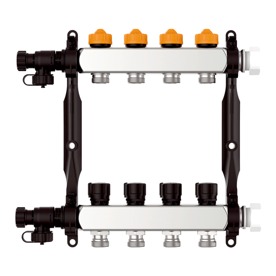
    Transport et stockage Transport et stockage Un transport et un stockage inadéquats risquent de causer des dommages au produit. AVIS MANUTENTION INAPPROPRIÉE • Assurez-vous que les conditions ambiantes spécifiées sont respectées pen- dant le transport et le stockage. • Utilisez l'emballage d'origine pour le transport. •...
  • Page 51 Description du produit Description du produit Les circuits de chauffage se composent d'un départ et d'un retour. Aperçu Modèle standard Accessoires (option) A. Vanne retour 1. Vanne à sphère G1 B. Ligne de distribution (dépendante 2. Coude de fixation de la variante) 3.
  • Page 52: Description Du Produit

    Description du produit Dimensions et raccordements Circuits de chauffage Distance A 79 129 129 129 129 179 179 179 229 229 229 Distance B 100 100 100 150 200 200 200 250 250 300 300 DistanceC 76 126 126 126 126 176 176 176 176 226 Distance D 23 123 123 123 123 173 Distance E 34...
  • Page 53 Description du produit 30 mm 46 mm 79 mm ProCalida® EF 1...
  • Page 54 Description du produit Fonctionnement Le produit distribue le liquide dans les tuyauteries. Caractéristiques techniques Paramètre Valeur Caractéristiques générales Raccordement principal G1 avec écrou-raccord Filetage mâle G1 Raccordement du circuit de chauffage G eurocône Température et pression de service 60 °C max. en cas de 6 bar 90 °C max.
  • Page 55: Échaudures Causées Par Des Liquides Chauds

    Montage Montage Le produit est monté dans une armoire de distribution, en surface ou encas- tré, au mur.  Vérifiez l'absence de pression dans le système. AVERTISSEMENT ÉCHAUDURES CAUSÉES PAR DES LIQUIDES CHAUDS Les liquides dans les installations de chauffage sont sous haute pression et peut atteindre des températures dépassant 100 °C.
  • Page 56 Montage  Assurez-vous que le col- lecteur supérieur (A) est légèrement incliné et que B est droit. 2. Relevez la barre vers le haut et enclenchez-la (clic). 3. Fixez la barre à l'aide d'une vis. ProCalida® EF 1...
  • Page 57: Monter Une Soupape De Décharge

    Montage Monter une soupape de décharge Si vous montez une soupape de décharge, le système ne peut plus être rem- pli et rincé aux capuchons terminaux. AVIS MANUTENTION INAPPROPRIÉE • Assurez-vous que les robinets de remplissage et vidange KFE soient instal- lés avant de remplir et de rincer le système.
  • Page 58 Montage 2. Remplacez la tige par la vis de fermeture (D). Si un capuchon terminal est installé : Remplacez le capuchon ter- minal (E) par un capuchon terminal avec raccord tuyau (F). ProCalida® EF 1...
  • Page 59 Montage 3. Montez la soupape de décharge. 4. Assurez-vous que le sens de passage est correct (G). 5. Réglez la pression sur la soupape de décharge (H). - Réglable en continue 0,1 bar - 0,5 bar. ProCalida® EF 1...
  • Page 60 Montage p : Pression différentielle [mbar] Q : Débit volumique [l/h] Figure 1: Diagramme pression différentielle sur la soupape de décharge ProCalida® EF 1...
  • Page 61: Mise En Service

    Mise en service Mise en service Mise en service 1. Raccordez le tuyau (D) au capuchon terminal avec le raccord de tuyau ou au robi- net de remplissage et vidange KFE (E). 2. Ouvrez le volant à main blanc pour le remplissage et le rinçage.
  • Page 62: Effectuer Le Test De Pression Et De Fonctionnement

    Mise en service 10.Ouvrez la vis de purge d'air dʼun tour maximum (F). Max. 1 x Effectuer le test de pression et de fonctionnement 1. Effectuez un test de pression avec 6 bar. - La pression du système doit rester constante pendant au moins deux heures (chute de pression maximale 0,2 bar) 2.
  • Page 63: Sans Débitmètre

    Mise en service 6.3.2 Sans débitmètre p : Perte de pression [mbar] Q : Débit volumique [l/h] Figure 2: Diagramme de détermination du débit 1. Fermez la vanne de départ. 2. Réglez l'anneau de réglage sur la valeur de réglage (A) selon figure 2.
  • Page 64: Garantie

    Avant de retourner le produit, il faut que vous preniez contact avec nous  (service@afriso.de). Garantie Les informations sur la garantie figurent dans nos "Conditions générales de vente" sur le site www.afriso.com ou dans votre contrat d'achat. ProCalida® EF 1...
  • Page 65: Pièces Inadaptées

    Pièces détachées et accessoires Pièces détachées et accessoires AVIS PIÈCES INADAPTÉES • N'utilisez que des accessoires et des pièces détachées d'origine provenant du fabricant. La non-observation de ces instructions peut causer des dommages maté- riels. Produit Désignation de l'article Référence Figure Collecteur de circuits de chauffage...
  • Page 66: Pièces Détachées Et Accessoires

    Pièces détachées et accessoires Désignation de l'article Référence Figure Actionneur TSA-02 78882 230 V NC Actionneur TSA-03 78871 230 V NC avec interrupteur de fin de course Ensemble soupape de décharge 80839 Ensemble thermomètre 80840 ProCalida® EF 1...
  • Page 67 Manual de  instrucciones Distribuidor de calefacción ProCalida® Tipo: EF1 Copyright 2020 AFRISO-EURO-INDEX GmbH. Todos los derechos reservados. Lindenstraße 20 74363 Güglingen Teléfono +49 7135 102-0 Servicio +49 7135 102-211 Telefax +49 7135 102-147 info@afriso.com www.afriso.com Versión: 08.2020.0 ID: 900.000.0497...
  • Page 68 Sobre este manual de instrucciones Sobre este manual de instrucciones Este manual de instrucciones describe el distribuidor de calefacción „ProCa- lida® EF 1“ (en lo sucesivo también referido como "producto"). Este manual de instrucciones forma parte del producto. • No utilice el producto antes de haber leído y entendido este manual de instrucciones completamente.
  • Page 69 Informaciones de seguridad Informaciones de seguridad Advertencias y clases de peligro Este manual de instrucciones comprende advertencias que indican peligros y riesgos potenciales. Además de las prescripciones contenidas en este manual de instrucciones se observarán todas las disposiciones, normas e indicaciones de seguridad en el lugar de utilización del producto.
  • Page 70: Informaciones De Seguridad

    Informaciones de seguridad Uso previsto Este producto se emplea exclusivamente para la distribución de medios en sistemas de calefacción de superficie y de refrigeración en edificios empleando los medios siguientes: • Agua de calefacción según VDI 2035 • Mezclas de agua-glicol con una adición máxima de un 50% Otras aplicaciones no son apropiadas y provocan peligros.
  • Page 71 Informaciones de seguridad Mal uso razonablemente previsible El producto no se aplicará en los siguientes casos y para los fines siguientes: • Distribución de agua potable Calificación del personal Trabajos en y con este producto serán sólo realizados por técnicos especia- lizados que conocen y entienden el contenido de este manual de instruccio- nes y todos los documentos pertenecientes al producto.
  • Page 72: Transporte Y Almacenaje

    Transporte y almacenaje Transporte y almacenaje El producto puede resultar dañado por transporte y almacenaje inadecuado. AVISO MANEJO INADECUADO • Asegúrese de que durante el transporte y el almacenaje del producto se observan las condiciones ambientales especificadas. • Utilice para el transporte el embalaje original. •...
  • Page 73 Descripción del producto Descripción del producto Los circuitos de calefacción comprenden una salida y un retorno. Sinopsis Versión estándar Accesorio (opcional) A. Válvula de retorno 1. Válvula de bola G1 B. Grupo de distribución (según 2. Codo conector variante) 3. Purgador rápido C.
  • Page 74: Descripción Del Producto

    Descripción del producto Dimensiones y conexiones Circuitos de calefac- ción Distancia A 79 129 129 129 129 179 179 179 229 229 229 Distancia B 100 100 100 150 200 200 200 250 250 300 300 Distancia C 76 126 126 126 126 176 176 176 176 226 Distancia D 23 123 123 123 123 173 Distancia E 34...
  • Page 75 Descripción del producto 30 mm 46 mm 79 mm ProCalida® EF 1...
  • Page 76 Descripción del producto Funcionamiento El producto distribuye el medio a los bucles. Datos técnicos Parámetros Valor Datos generales Conexión principal G1 con tuerca de unión Rosca exterior G1 Conexión del circuito de calefacción Eurokonus Temperatura y presión de funciona- Máx. 60 °C con 6 bar miento Máx.
  • Page 77 Montaje Montaje El producto se monta en una caja de distribución en pared o bajo revoque.  Asegúrese de que la instalación está sin presión. ADVERTENCIA ESCALADURAS POR LÍQUIDO CALIENTE Medios en instalaciones de calefacción están bajo presión alta, las temperatu- ras pueden exceder los 100°C.
  • Page 78 Montaje  Asegúrese de que el dis- tribuidor superior (A) está fijado con una ligera incli- nación, distribuidor B recto. 2. Pliega la abrazadera hacia arriba y déjela enclavar (clic). 3. Fije la abrazadera con un tornillo. ProCalida® EF 1...
  • Page 79: Montar Válvula De Rebose

    Montaje Montar válvula de rebose Montando una válvula de rebose, ya no se puede llenar o lavar la instalación en las tapas de extremo. AVISO MANEJO INADECUADO • Asegúrese de que están montados los grifos de llenado y vaciado antes de llenar o limpiar la instalación.
  • Page 80 Montaje 2. Sustituya el husillo por un tornillo de cierre (D). Cuando está montada una tapa de extremo: Sustituya la tapa de extremo (E) por una tapa con cone- xión de tubo flexible (F). ProCalida® EF 1...
  • Page 81 Montaje 3. Monte la válvula de rebose. 4. Observe la dirección del caudal (G). 5. Ajuste la presión en la vál- vula de rebose (H). - Con regulación continua 0,1 bar - 0,5 bar. ProCalida® EF 1...
  • Page 82 Montaje p: Presión diferencial [mbar] Q: Flujo volumétrico [l/h] Figura 1: Diagrama de presión diferencial en la válvula de rebose ProCalida® EF 1...
  • Page 83: Puesta En Marcha Del Producto

    Puesta en marcha Puesta en marcha Puesta en marcha del producto 1. Conecte el tubo flexible (D) en la tapa de extremo con la conexión de tubo flexible o en el grifo de llenado y vaciado (E). 2. Abra el pomo blanco para llenar o limpiar.
  • Page 84 Puesta en marcha 10.Abra el tornillo de purga con un giro máximo (F). Máx. 1 x Efectúe la prueba de presión y de funcionamiento 1. Efectúe la prueba de presión con 6 bar. - La presión de instalación debe mantenerse constante durante por lo menos dos horas (caída de presión máxima 0,2 bar) 2.
  • Page 85 Puesta en marcha 6.3.2 Sin caudalímetro p: Pérdida de presión [mbar] Q: Flujo volumétrico [l/h] Figura 2: Diagrama para la determinación del caudal 1. Cierra la válvula de salida. 2. Ajuste el valor de ajuste (A) según figura 2 en el anillo de ajuste. 3.
  • Page 86 2. Elimine el producto. Reexpedición Ante la reexpedición del producto, pónganse en contacto con nosotros  (service@afriso.de). Garantía Para informaciones acerca de la garantía, consulte nuestras Condiciones Generales en Internet bajo www.afriso.com o en el contrato de compraventa. ProCalida® EF 1...
  • Page 87 Piezas de repuesto y accesorios Piezas de repuesto y accesorios AVISO PIEZAS INADECUADAS • Emplee únicamente piezas de repuesto y accesorios del fabricante. El incumplimiento de estas prescripciones puede causar daños materia- les. Producto Denominación de artículo Nº art. Figura Distribuidor de calefacción...
  • Page 88: Piezas De Repuesto Y Accesorios

    Piezas de repuesto y accesorios Denominación de artículo Nº art. Figura Actuador TSA-02 78882 230 V NC Actuador TSA-03 78871 230 V NC con interruptor final de carrera Kit de válvula de rebose 80839 Kit de termómetro 80840 ProCalida® EF 1...
  • Page 89 Istruzioni per l’uso Modulo di distribuzione per riscaldamenti ProCalida® Tipo: EF1 Copyright 2020 AFRISO-EURO-INDEX GmbH. Tutti i diritti sono riservati. Lindenstraße 20 74363 Güglingen Telefono +49 7135 102-0 Service +49 7135 102-211 Telefax +49 7135 102-147 info@afriso.com www.afriso.com Versione: 08.2020.0...
  • Page 90 Su queste Istruzioni per l'uso Su queste Istruzioni per l'uso Queste Istruzioni per l'uso descrivono il modulo di distribuzione per riscalda- menti "ProCalida ® EF 1" (nel proseguio anche "prodotto"). Le presenti Istru- zioni per lʼuso costituiscono parte del prodotto. •...
  • Page 91 Informazioni sulla sicurezza Informazioni sulla sicurezza Avvertenze e classi di pericolosità Queste Istruzioni per l'uso contengono avvertenze che richiamano l'atten- zione a pericoli e rischi. In aggiunta alle avvertenze riportate nelle Istruzioni per l'uso sono da rispettare tutte le disposizioni, prescrizioni e norme di sicu- rezza vigenti sul posto d'impiego del prodotto.
  • Page 92: Informazioni Sulla Sicurezza

    Informazioni sulla sicurezza Uso conforme Questo prodotto è idoneo esclusivamente alla distribuzione di fluidi in impianti di riscaldamento a pavimento o sistemi di refrigerazione in edifici che utilizzano i seguenti fluidi: • acqua di riscaldamento secondo VDE 2035 • miscele di acqua-glicole con max. 50% di additivo Ogni altro utilizzo è...
  • Page 93 Informazioni sulla sicurezza Uso improprio prevedibile Il prodotto non può essere utilizzato in particolar modo nei seguenti casi e per i seguenti scopi: • distribuzione di acqua potabile Qualifica del personale I lavori con e a questo prodotto sono prerogativa di personale specializzato, che conosce ed ha capito i contenuti di queste Istruzioni per l'uso e tutta la documentazione che fa parte del prodotto.
  • Page 94: Trasporto E Magazzinaggio

    Trasporto e magazzinaggio Trasporto e magazzinaggio I prodotto può riportare danni da trasporto e magazzinaggio non adeguato. AVVISO UTILIZZO IMPROPRIO • Assicurare che le condizioni ambientali specificate per il trasporto e il magaz- zinaggio siano rispettate. • Per il trasporto, utilizzate l'imballaggio originale. •...
  • Page 95 Descrizione del prodotto Descrizione del prodotto I circuiti di riscaldamento comprendono una mandata e un ritorno. Riassuntivo Versione standard Accessori (opzionali) A. Valvola ritorno 1. Rubinetto a sfera G1 B. Tubatura di distribuzione (a 2. Raccordo a gomito dipendere 3. Sfiato rapido dalla variante) 4.
  • Page 96: Descrizione Del Prodotto

    Descrizione del prodotto Dimensioni e attacchi Circuiti di riscalda- mento Distanza A 79 129 129 129 129 179 179 179 229 229 229 Distanza B 100 100 100 150 200 200 200 250 250 300 300 Distanza C 76 126 126 126 126 176 176 176 176 226 Distanza D 23 123 123 123 123 173 Distanza E 34...
  • Page 97 Descrizione del prodotto 30 mm 46 mm 79 mm ProCalida® EF 1...
  • Page 98: Specifiche Tecniche

    Descrizione del prodotto Funzione Il prodotto distribuisce il fluido nei circuiti tubieri. Specifiche tecniche Parametri Valore Dati generali Collegamento circuito principale G1 con dado per raccordi Filettatura esterna G1 Collegamento circuito di riscaldamento G Eurokonus Temperatura e pressione dʼesercizio max. 60 °C a 6 bar max.
  • Page 99 Montaggio Montaggio Il prodotto viene montato in un armadio di distribuzione a scomparsa o a muro oppure direttamente su parete.  Assicuratevi che l'impianto non sia in pressione. AVVERTIMENTO SCOTTATURA DA LIQUIDI CALDI I fluidi negli impianti di riscaldamento sono in forte pressione e possono raggiun- gere temperature di oltre 100 °C.
  • Page 100 Montaggio  Assicuratevi che il distri- butore superiore (A) sia posizionate leggermente inclinato e il distributore B sia diritto. 2. Ribaltate l'archetto verso l'alto per farlo incastrare (clic). 3. Fissate l'archetto con una vite. ProCalida® EF 1...
  • Page 101 Montaggio Montare la valvola di troppopieno. Quando sullʼimpianto viene montata una valvola di troppo pieno, lʼimpianto non può più essere riempito e sciacquato dalle cappe terminali. AVVISO UTILIZZO IMPROPRIO • Assicuratevi che siano montati i rubinetti di riempimento e scarico prima di riempire o sciacquare l'impianto.
  • Page 102 Montaggio 2. Sostituire l'alberino con la vite di chiusura (D). Se è montata una cappa terminale: Sostituire la cappa terminale (E) con una cappa terminale dotata di raccordo per tubi (F). ProCalida® EF 1...
  • Page 103 Montaggio 3. Montare la valvola di trop- popieno. 4. Rispettare la direzione di flusso(G). 5. Impostare la pressione sulla valvola di troppo- pieno (H). - Regolazione continua da 0,1 a 0,5 bar. ProCalida® EF 1...
  • Page 104 Montaggio p: pressione differenziale [mbar] Q: Portata in volume [l/h] Figura 1: Diagramma pressione differenziale presso la valvola di troppopieno ProCalida® EF 1...
  • Page 105: Messa In Funzione

    Messa in funzione Messa in funzione Messa in funzione del prodotto 1. Collegare il tubo (D) alla cappa terminale con rac- cordo tubiero o al rubinetto di riempimento e scarico (E). 2. Aprire il volantino bianco per riempire e sciacquare. 3.
  • Page 106 Messa in funzione 10.Aprire la vite di sfiato di max. 1 rotazione completa (F). Max. 1 x Eseguire la prova di pressione e il test di funzionamento 1. Eseguire una prova di pressione a 6 bar. - La pressione nellʼimpianto deve rimanere costante per almeno 2 ore senza calare (calo max.
  • Page 107 Messa in funzione 6.3.2 Senza contatore volumetrico p: perdita di pressione [mbar] Q: portata in volume [l/h] Figura 2: Diagramma per determinare la portata 1. Chiudere la valvola di mandata. 2. Impostare il valore (A) con lʼanello di regolazione come rappresen- tato in figura 2.
  • Page 108 Rispedizione al fornitore Prima di rispedire il prodotto, mettetevi in contatto con noi  (service@afriso.de). Garanzia Le informazioni sulla garanzia sono riportate nelle condizioni di contratto generali in internet sul sito www.afriso.com o nel vostro contratto d'acquisto. ProCalida® EF 1...
  • Page 109 Ricambi e accessori Ricambi e accessori AVVISO COMPONENTI NON IDONEI • Utilizzare solo pezzi di ricambio e accessori del produttore. La mancata osservanza di queste indicazioni può causare danni materiali. Prodotto Nome articolo Art. N° Figura Modulo di distribuzione per riscalda- 80822 ...
  • Page 110: Ricambi E Accessori

    Ricambi e accessori Nome articolo Art. N° Figura Attuatore TSA-02 78882 230 V NC Attuatore TSA-03 78871 230 V NC con finecorsa Set valvole trabocco 80839 Set termometri 80840 ProCalida® EF 1...
  • Page 111 Manual de instruções Distribuidor de circuito de aquecimento ProCalida® Tipo: EF1 Copyright 2020 AFRISO-EURO-INDEX GmbH. Todos os direitos reservados. Lindenstraße 20 74363 Güglingen Telefon +49 7135 102-0 Service +49 7135 102-211 Telefax +49 7135 102-147 info@afriso.com www.afriso.com Versão: 08.2020.0 ID: 900.000.0497...
  • Page 112 Sobre este manual de instruções Sobre este manual de instruções Este manual de instruções descreve o distribuidor de circuito de aqueci- mento «ProCalida® EF 1» (a seguir designado por «produto»). Este manual de instruções é parte integrante do produto. • Só...
  • Page 113 Informações sobre segurança Informações sobre segurança Indicações de aviso e classes de perigo Neste manual de instruções encontram-se indicações de aviso que alertam para potenciais perigos e riscos. Para além das instruções neste manual, têm de ser cumpridas todas as disposições, normas e regras de segurança em vigor no local de utilização do produto.
  • Page 114: Informações Sobre Segurança

    Informações sobre segurança Utilização correta Este produto foi concebido exclusivamente para a distribuição de produtos em sistemas de aquecimento de superfícies e sistemas de refrigeração em edifícios mediante utilização dos seguintes produtos: • Água de aquecimento de acordo com a norma VDI 2035 •...
  • Page 115 Informações sobre segurança Má utilização previsível O produto não pode ser aplicado especialmente nos seguintes casos e para os seguintes fins: • Distribuição de água potável Qualificações do pessoal Os trabalhos no e com este produto só podem ser executados por técnicos qualificados que conheçam e compreendam o conteúdo deste manual de instruções e de todos os documentos pertencentes ao produto.
  • Page 116: Transporte E Armazenamento

    Transporte e armazenamento Transporte e armazenamento O produto pode ser danificado pelo transporte ou armazenamento inade- quado. AVISO MANUSEAMENTO INADEQUADO • Certifique-se de que, durante o transporte e o armazenamento do produto, são respeitadas as condições ambientais especificadas. • Utilize a embalagem original para o transporte. •...
  • Page 117: Vista Geral

    Descrição do produto Descrição do produto Os circuitos de aquecimento consistem em um avanço e um retorno. Vista geral Modelo standard Acessórios (opcional) A. Válvula de retorno 1. Válvula de esfera G1 B. Linha de distribuidores (depen- 2. Conector angular dendo da variante) 3.
  • Page 118: Descrição Do Produto

    Descrição do produto Dimensões e ligações Circuitos de aqueci- mento Distância A 79 129 129 129 129 179 179 179 229 229 229 Distância B 100 100 100 150 200 200 200 250 250 300 300 Distância C 76 126 126 126 126 176 176 176 176 226 Distância D 23 123 123 123 123 173 Distância E 34...
  • Page 119 Descrição do produto 30 mm 46 mm 79 mm ProCalida® EF 1...
  • Page 120: Dados Técnicos

    Descrição do produto Função O produto distribui o meio nas serpentinas da tubagem. Dados técnicos Parâmetro Valor Dados gerais Conexão principal G1 com porca de capa Rosca macho G1 Conexão de circuito de aquecimento eurocone Temperatura e pressão de serviço Máx.
  • Page 121 Montagem Montagem O produto é montado num armário de distribuição, à superfície ou embutido, na parede.  Certifique-se de que o equipamento está despressurizado. ADVERTÊNCIA ESCALDADURAS DEVIDO A LÍQUIDO QUENTE Os meios (líquidos) em instalações de aquecimento estão sob uma elevada pressão e podem atingir temperaturas superiores a 100 °C.
  • Page 122 Montagem  Certifique-se de que o dis- tribuidor superior (A) está fixado em posição ligeira- mente inclinada e o distri- buidor B em posição reta. 2. Vire o aro para cima e encaixe-o (clique). 3. Fixe o aro com um para- fuso.
  • Page 123: Válvula De Descarga

    Montagem Válvula de descarga Em caso de montagem de uma válvula de descarga, deixa de ser possível encher e lavar o equipamento nas tampas terminais. AVISO MANUSEAMENTO INADEQUADO • Certifique-se de que as válvulas KFE estão montadas antes de encher ou lavar o equipamento.
  • Page 124 Montagem 2. Substitua o fuso pelo parafuso de tampona- mento (D). Se estiver montada uma tampa terminal: Substitua a tampa terminal (E) por uma tampa terminal com conexão de tubo (F). ProCalida® EF 1...
  • Page 125 Montagem 3. Monte a válvula de des- carga. 4. Preste atenção à direção do fluxo (G). 5. Ajuste a pressão na vál- vula de descarga (H). - Ajuste progressivo 0,1 bar - 0,5 bar. ProCalida® EF 1...
  • Page 126 Montagem p: Pressão diferencial [mbar] Q: Fluxo volumétrico [l/h] Figura 1: Diagrama Pressão diferencial na válvula de descarga ProCalida® EF 1...
  • Page 127: Colocar O Produto Em Funcionamento

    Colocação em funcionamento Colocação em funcionamento Colocar o produto em funcionamento 1. Conecte o tubo (D) à tampa terminal com a conexão de tubo ou à válvula KFE (E). 2. Abra a manivela branca para encher e lavar. 3. Abra a válvula de retorno do primeiro circuito de aqueci- mento (A).
  • Page 128: Colocação Em Funcionamento

    Colocação em funcionamento 10.Abra o parafuso de purga de ar com máximo de uma volta (F). Máx. 1 x Executar ensaio de pressão e teste de funcionamento 1. Execute um ensaio de pressão com 6 bar. - A pressão do equipamento tem de permanecer constante por pelo menos duas horas (queda de pressão máxima de 0,2 bar) 2.
  • Page 129 Colocação em funcionamento 6.3.2 Sem fluxímetro p: Perda de pressão [mbar] Q: Fluxo volumétrico [l/h] Figura 2: Diagrama para determinar o fluxo 1. Feche a válvula de avanço. 2. Ajuste o valor de ajuste (A) de acordo com a figura 2 no anel de ajuste.
  • Page 130 Antes de devolver o produto, tem de entrar em contacto connosco  (service@afriso.de). Garantia Pode consultar informações sobre a garantia nas nossas Condições Gerais, que se encontram na Internet, em www.afriso.com, ou no seu contrato de compra e venda. ProCalida® EF 1...
  • Page 131 Peças sobresselentes e acessórios Peças sobresselentes e acessórios AVISO PEÇA INAPROPRIADA • Utilize exclusivamente pecas sobresselentes e acessórios originais do fabri- cante. O não cumprimento desta instrução pode resultar em danos materiais. Produto Designação do produto N.° de art.º Figura Distribuidor de circuito de aqueci- 80822 ...
  • Page 132: Peças Sobresselentes E Acessórios

    Peças sobresselentes e acessórios Designação do produto N.° de art.º Figura Atuador TSA-02 78882 230 V NC Atuador TSA-03 78871 230 V NC com fim de curso Conjunto válvula de descarga 80839 Conjunto termómetro 80840 ProCalida® EF 1...
  • Page 133: Instrukcja  Eksploatacji

    Instrukcja  eksploatacji Rozdzielacz obiegu grzewczego ProCalida® Typ: EF1 Copyright 2020 AFRISO-EURO-INDEX GmbH. Wszystkie prawa zastrzeżone. Lindenstraße 20 74363 Güglingen telefon +49 7135 102-0 serwis +49 7135 102-211 telefaks +49 7135 102-147 info@afriso.com www.afriso.com Version: 08.2020.0 ID: 900.000.0497...
  • Page 134: Objaśnienia Do Niniejszej Instrukcji Eksploatacji

    Objaśnienia do niniejszej instrukcji eksploatacji Objaśnienia do niniejszej instrukcji eksploatacji Niniejsza instrukcja eksploatacji opisuje rozdzielacz obiegu grzewczego „ProCalida® EF 1“ (poniżej zwany także „produktem“). Niniejsza instrukcja eks- ploatacji jest częścią produktu. • Produkt wolno użytkować dopiero po całkowitym przeczytaniu i pełnym zro- zumieniu instrukcji eksploatacji.
  • Page 135 Informacje na temat bezpieczeństwa Informacje na temat bezpieczeństwa Wskazówki ostrzegawcze i klasy zagrożenia Niniejsza instrukcja eksploatacji zawiera wskazówki ostrzegawcze zwracające uwagę na potencjalne zagrożenia oraz ryzyka. Poza zaleceniami zawartymi w niniejszej instrukcji eksploatacji trzeba przestrzegać wszystkich warunków, norm oraz przepisów bezpieczeństwa obowiązujących w miejscu użytkowania produktu.
  • Page 136: Stosowanie Zgodne Z Przeznaczeniem

    Informacje na temat bezpieczeństwa Stosowanie zgodne z przeznaczeniem Niniejszy produkt przeznaczony jest wyłącznie do rozprowadzania mediów w systemach ogrzewania powierzchniowego oraz systemach chłodzenia w budynkach przy stosowaniu następujących mediów: • wody grzewczej zgodnej z wymogami VDI 2035, • mieszanin wody i glikolu z maksymalną domieszką 50 %. Inny rodzaj zastosowania nie jest zgodny z przeznaczeniem i powoduje powstawanie zagrożeń.
  • Page 137 Informacje na temat bezpieczeństwa Przewidywalne błędne stosowanie Produktu nie wolno stosować w szczególności w następujących przypadkach i do następujących celów: • do rozdzielania przepływu wody pitnej. Kwalifikacje personelu Czynności wykonywane przy produkcie oraz z jego pomocą mogą wykonywać wyłącznie wykwalifikowani pracownicy, którzy zapoznali się z niniejszą instruk- cją...
  • Page 138: Transport I Składowanie

    Transport i składowanie Transport i składowanie Niewłaściwy transport i składowanie mogą spowodować uszkodzenie pro- duktu. WSKAZÓWKA NIEWŁAŚCIWA OBSŁUGA • Należy upewnić się, że podczas transportu i składowania produktu dotrzymy- wane są warunki otoczenia wyszczególnione w specyfikacji. • Do celów transportowych należy wykorzystywać oryginalne opakowanie. •...
  • Page 139: Opis Produktu

    Opis produktu Opis produktu Obiegi grzewcze składają się z zasilania i powrotu. Przegląd Wersja standardowa Wyposażenie dodatkowe (opcjonalne) A. zawór powrotny 1. zawór kulowy G1 B. sekcja rozdzielacza (w zależności 2. kolano montażowe od wariantu) 3. odpowietrznik automatyczny 4. element dystansowy 60 mm C.
  • Page 140: Wymiary I Przyłącza

    Opis produktu Wymiary i przyłącza Obiegi grzewcze odstęp A 129 129 129 129 179 179 179 229 229 229 odstęp B 100 100 100 150 200 200 200 250 250 300 300 odstęp C 126 126 126 126 176 176 176 176 226 odstęp D 123 123 123 123 173 odstęp E...
  • Page 141 Opis produktu 30 mm 46 mm 79 mm ProCalida® EF 1...
  • Page 142 Opis produktu Działanie Produkt rozdziela medium w pętlach rurociągowych. Dane techniczne Parametr Wartość Dane ogólne przyłącze główne G1 z nakrętką złączkową nasadową G1 gwint zewnętrzny przyłącze do obiegu grzewczego złączka typu „Eurokonus” temperatura i ciśnienie robocze maksymalnie 60 °C przy 6 bar maksymalnie 90 °C przy 3 bar przepływ rozdzielacza maksymalnie 3,5 m 3,5 m...
  • Page 143 Montaż Montaż Montaż produktu odbywa się na ścianie, w szafce rozdzielczej, natynkowo lub podtynkowo.  Należy upewnić się, że instalacja nie znajduje się pod ciśnieniem. OSTRZEŻENIE GORĄCA CIECZ Media w instalacjach grzewczych znajdują się się pod wysokim ciśnieniem i mogą osiągać...
  • Page 144 Montaż  Należy upewnić się, że roz- dzielacz górny A jest zamocowany w pozycji lekko skośnej, a rozdzie- lacz B w pozycji prostej. 2. Odchylić obejmę w kie- runku górnym aż do zaskoczenia blokady (zatrzask). 3. Przykręcić obejmę wkrę- tem. ProCalida®...
  • Page 145 Montaż Montaż zaworu przelewowego W razie montażu zaworu przelewowego instalacji nie można już napełniać i przepłukiwać za pośrednictwem nakrętek końcowych. WSKAZÓWKA NIEWŁAŚCIWA OBSŁUGA • Przed napełnieniem lub przepłukaniem instalacji należy upewnić się, że zamo- nowano zawory spustowo-napełniające. Nieprzestrzeganie niniejszych zaleceń może doprowadzić do powstania szkód materialnych.
  • Page 146 Montaż 2. Zastąpić trzpień zaślepką gwintowaną (D). Jeśli zainstalowana jest nakrętka końcowa: Nakrętkę końcową (E) zastą- pić nakrętką końcową z przy- łączem wężowym (F). ProCalida® EF 1...
  • Page 147 Montaż 3. Zamontować zawór prze- lewowy. 4. Przestrzegać kierunku przepływu (G). 5. Ustawić ciśnienie na zawo- rze przelewowym (H). - Płynna regulacja 0,1 bar - 0,5 bar. ProCalida® EF 1...
  • Page 148 Montaż p: ciśnienie różnicowe [mbar] Q: natężenie przepływu [l/h] Ilustracja 1: Wykres ciśnienia różnicowego na zaworze przelewowym ProCalida® EF 1...
  • Page 149: Uruchamianie Produktu

    Uruchamianie Uruchamianie Uruchamianie produktu 1. Wąż (D) podłączyć do nakrętki końcowej z przyłą- czem wężowym lub do zaworu spustowo-napełnia- jącego (E). 2. Otworzyć białe pokrętło do napełniania i przepłukiwania. 3. Otworzyć zawór powrotny pierwszego obiegu grzew- maks czego (A). ymaln 4.
  • Page 150 Uruchamianie 10.Otworzyć śrubę odpowie- trzającą maksymalnie jed- nym obrotem (F). maksy Wykonanie próby ciśnieniowej i kontroli działania 1. Przeprowadzić próbę ciśnieniową przy ciśnieniu 6 bar. - Ciśnienie w instalacji musi pozostawać na stałym poziomie przez co naj- mniej dwie godziny (maksymalny spadek ciśnienia 0,2 bar). 2.
  • Page 151 Uruchamianie 6.3.2 Bez przepływomierza p: spadek ciśnienia [mbar] Q: natężenie przepływu [l/h] Ilustracja 2: Wykres do określania natężenia przepływu 1. Zamknąć zawór zasilający. 2. Ustawić wartość (A) na pierścieniu nastawczym według ilustracji 2. 3. Otworzyć zawór zasilający. ProCalida® EF 1...
  • Page 152: Usuwanie Usterek

    1. Wykonać demontaż produktu (patrz rozdział "Montaż" w odwrotnej kolejno- ści). 2. Produkt poddać utylizacji. Zwrot Przed zwrotną wysyłką produktu wymagany jest kontakt z producentem (service@afriso.de). Gwarancja Informacje dotyczące gwarancji są dostępne w naszych Ogólnych Warunkach Handlowych w internecie pod adresem www.afriso.com lub w umowie kupna. ProCalida® EF 1...
  • Page 153 Części zamienne i wyposażenie dodatkowe Części zamienne i wyposażenie dodatkowe WSKAZÓWKA NIEWŁAŚCIWE CZĘŚCI • Należy stosować wyłącznie oryginalne części zamienne i wyposażenie dodat- kowe producenta. Nieprzestrzeganie niniejszego zalecenia może doprowadzić do powstania szkód materialnych. Produkt Nazwa artykułu Numer artykułu Ilustracja rozdzielacz obiegu grzewczego...
  • Page 154: Części Zamienne I Wyposażenie Dodatkowe

    Części zamienne i wyposażenie dodatkowe Nazwa artykułu Numer artykułu Ilustracja siłownik TSA-02 78882 230 V NC siłownik TSA-03 78871 230 V NC z wyłącznikiem krańcowym zestaw zaworu przelewowego 80839 zestaw termometru 80840 ProCalida® EF 1...

Table des Matières