Table des Matières
Publicité
Les langues disponibles
Les langues disponibles
Liens rapides
www.power-one.com
Aurora
®
Power Service
USA
Aurora
Power Service
France
®
Aurora
Power Service
Germany
®
Aurora
Power Service
Italy
®
Aurora
®
Power Service
Spain
Aurora
®
Power Service
Middle East
Aurora
®
Power Service
Australia
Aurora
®
Power Service
China
Aurora
®
Power Service
Singapore
Aurora
®
Power Service
Malaysia
R
v e
1 .
3 .
-
A
u
o r
a r
®
is a trademark by Power-One - Product is subject to technical improvements
BCB.00034.1
877-261-1374
00 800 00 28 76 72
0800-2200211
00 800 00 28 76 72
00 800 00 28 76 72
00 800 00 28 76 72
+61 2 9735 3111
+86 755 2988 5888
+65 6896 3363
+603-8025 9963
INSTALLATION AND CONFIGURATION MANUAL
MANUALE D'INSTALLAZIONE E CONFIGURAZIONE
INSTALLATIONS UND KONFIGURATIONSMANUAL
MANUEL D'UTILISATION ET D'INSTALLATION
Mod Number:
PVI-10.0-I-OUTD-400
PVI-10.0-I-OUTD-S-400
PVI-12.0-I-OUTD-400
PVI-12.0-I-OUTD-S-400
Publicité
Chapitres
Table des Matières

Manuels Connexes pour Aurora PVI-10.0-I-OUTD-400


Sommaire des Matières pour Aurora PVI-10.0-I-OUTD-400
- Page 1 Power Service Malaysia +603-8025 9963 INSTALLATION AND CONFIGURATION MANUAL MANUALE D’INSTALLAZIONE E CONFIGURAZIONE INSTALLATIONS UND KONFIGURATIONSMANUAL MANUEL D'UTILISATION ET D'INSTALLATION Mod Number: PVI-10.0-I-OUTD-400 PVI-10.0-I-OUTD-S-400 ® is a trademark by Power-One - Product is subject to technical improvements PVI-12.0-I-OUTD-400 BCB.00034.1 PVI-12.0-I-OUTD-S-400...
- Page 2 ® AURORA Photovoltaic Inverters INSTALLATION AND OPERATING MANUAL Model number: PVI-10.0/12.0-I-OUTD(-S)-400 Rev. 1.3...
-
Page 3: Important Safety Instructions
Use and installation manual Page (PVI-10.0/12.0-I-OUTD(-S)-400 Rev:1.3) TABLE OF CHANGES Revision of Author Date Description of Changes Document Mastronardi F. 2011/06/01 First release Ferrini P. 2011/06/27 Various changes Statuti A. 2011/07/13 Various changes Statuti A. 2012/06/15 Various changes KEEP THESE INSTRUCTIONS! IMPORTANT SAFETY INSTRUCTIONS POWER-ONE: The total or partial reproduction of this document by any means is forbidden without the authorization of Power-One. -
Page 4: How To Use This Manual
Use and installation manual Page (PVI-10.0/12.0-I-OUTD(-S)-400 Rev:1.3) HOW TO USE THIS MANUAL This manual contains important instructions regarding safety and operation, which must be understood and carefully followed during the installation and maintenance of the equipment. In order to reduce the risk of electric shock and to be sure that the equipment is correctly installed and ready to operate, special safety symbols are used in this manual to highlight potential safety risks or useful information. -
Page 5: Useful Information And Safety Regulations
Page (PVI-10.0/12.0-I-OUTD(-S)-400 Rev:1.3) USEFUL INFORMATION AND SAFETY REGULATIONS FOREWORD The installation of AURORA must be performed in compliance with national and local regulations. AURORA has no spare parts. For all kinds of maintenance or repair, please contact the authorized repair centre closest to you. -
Page 6: Electrical Connection
Use and installation manual Page (PVI-10.0/12.0-I-OUTD(-S)-400 Rev:1.3) GENERAL When the inverter is operating, there can be parts that are live, or non-isolated, and in some cases also moving or rotating, and, in addition, some surfaces may become hot. Unauthorized removal of required protections, improper use, faulty installation or incorrect operation may cause serious damage to persons and things. - Page 7 Use and installation manual Page (PVI-10.0/12.0-I-OUTD(-S)-400 Rev:1.3) OPERATION The system in which the inverters are installed must be equipped with further control and protection devices, in accordance with the relative applicable safety standards, e.g. compliance with technical equipment, accident-prevention regulations, etc. Calibration variations are possible through the use of the operational software.
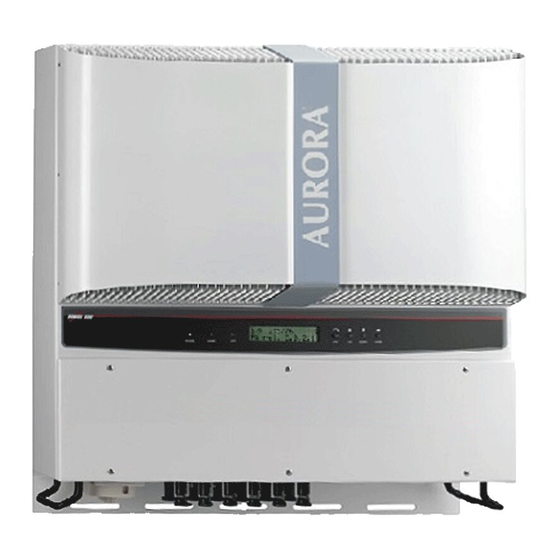
- Page 8 Use and installation manual Page (PVI-10.0/12.0-I-OUTD(-S)-400 Rev:1.3) PVI-10.0/12.0-I-OUTD(-S)-400 This documentation is only valid for the aforementioned versions of the inverter. Example of product name plate The name plate affixed to the inverter contains the following information: 1) Manufacturer code 2) Model code 3) Serial number 4) Week/Year of production...
-
Page 9: Table Des Matières
3.4.2 Procedure for accessing the internal terminal blocks by removing the front cover .................... 27 3.4.3 AC and DC cable selection ..............28 3.4.4 Installation of the AURORA inverter............. 29 3.4.5 Possible configurations of input channels ..........30 3.4.5.1 Connection with independent channels.......... - Page 10 Use and installation manual Page (PVI-10.0/12.0-I-OUTD(-S)-400 Rev:1.3) COMMISSIONING AND SWITCHING OFF THE INVERTER ....41 ..............41 OMMISSIONING PROCEDURE ............43 TART UP USING THE SIDE BUTTON ............... 43 DOWN PROCEDURE USER INTERFACE; MONITORING AND DATA TRANSMISSION ..44 ................44 SER INTERFACE MODE ................
- Page 11 Use and installation manual Page (PVI-10.0/12.0-I-OUTD(-S)-400 Rev:1.3) AURORA C ....77 UTOTEST PROCEDURE BY USING OMMUNICATOR DATA CHECK AND COMMUNICATION ..........82 RS-485 RJ45 ..82 ONNECTION THROUGH SERIAL PORT OR CONNECTORS 6.1.1 RS-485 serial port ................. 82 6.1.2 RJ45 connectors ................... 83 6.1.3 Daisy chain ..................
-
Page 12: Introduction
Page (PVI-10.0/12.0-I-OUTD(-S)-400 Rev:1.3) INTRODUCTION This document is a technical description of the AURORA photovoltaic inverter; the aim of this document is to provide the installer and user with the necessary information regarding the installation, operation and use of AURORA. PHOTOVOLTAIC ENERGY... -
Page 13: Description Of The System
Page (PVI-10.0/12.0-I-OUTD(-S)-400 Rev:1.3) DESCRIPTION OF THE SYSTEM AURORA is an inverter which is capable of feeding the power supply distribution grid with energy obtained from photovoltaic panels. The photovoltaic panels transform energy radiated by the sun into electrical energy in the form of direct current, or DC (through a photovoltaic field, also known as a PV generator);... - Page 14 Use and installation manual Page (PVI-10.0/12.0-I-OUTD(-S)-400 Rev:1.3) The models whose code end in -xx are equipped with an integrated DC switch 600V, 32 A, as shown in Fig. 1. Fig. 1 - Block diagram of inverter with integrated Dc switch...
-
Page 15: Arrays
Photovoltaic systems of a certain size can be composed of more than one array, connected to one or more AURORA inverters. By maximizing the number of panels inserted into each string, it is possible to reduce the cost and complexity of the plant connection system. - Page 16 In the event that the photovoltaic system exceeds the capacity of a single inverter, other AURORA inverters can be added to the system. Each of these inverters will be connected to an adequate section of the photovoltaic field on the DC side, and will be connected to the distribution grid on the AC side.
-
Page 17: Data Transmission And Monitoring
Radiomodule) to obtain a remote data display terminal, connected wirelessly. Technical description of AURORA Fig. 1 shows the block diagram of AURORA. The main blocks are the input DC- DC converters (known as “boosters”) and the output inverter. Both the DC-DC converters and the output inverter work at a high switching frequency to enable a compact design and a relatively low weight. -
Page 18: Protections
Each array is controlled by an MPPT control circuit. Due to the size and high efficiency of AURORA thermal dissipation system, this inverter guarantees operation at maximum power in a wide range of ambient temperatures. -
Page 19: Brand And Model Of Photovoltaic Panels
AURORA in the event that a ground fault is detected, and indicates the ground fault condition through a red LED located on the front panel. The AURORA inverter is equipped with terminals for the system ground conductors. -
Page 20: Installation
It is the client's responsibility to file a complaint with the carrier. Failure to do so may result in the loss of all warranty service rights for any reported damage; Keep AURORA original shipping package in case the device has to be returned for repair. -
Page 21: Inspecting The Package Contents
AURORA must be installed in a location chosen according to the following considerations: AURORA must be placed at a height from ground level, so that the display and status LEDs can be read easily. Choose a location which is protected from direct sunlight, and is well- ventilated. - Page 22 150mm .(6”) 50mm (2”) 200mm (8”) Fig. 4 - Installation location - Minimum clearances around AURORA RECOMMENDED POSITIONING Fig. 5 - Recommended installation of AURORA inverters NOTE: Although titled mounting is possible (see Fig. 6), please note that this may reduce performance (Derating), due to a reduction in heat dissipation.
- Page 23 AURORA inverters (see Fig. 5) When ambient temperature exceeds 50°C for PVI-10.0-I models, or 45°C for PVI- 12.0-I models, the inverter will self-derate the output power. In order to avoid overheating, always ensure that the airflow around AURORA is not blocked.
-
Page 24: Wall Mounting
Power-One recommends always using stainless steel screws. Attach AURORA to the springs (Part. D) present in the upper part of the bracket, by using the metal support fixed on the upper part of the rear of the inverter. This metal fin has points in correspondence to the fixing point on the bracket hooks (Part. - Page 25 Use and installation manual Page (PVI-10.0/12.0-I-OUTD(-S)-400 Rev:1.3) Part.A Part.B FRONT OF AURORA REAR OF AURORA Part.A Part.B Fig. 7 - Wall mounting of AURORA Part.D Part.D Part.C Part.C...
-
Page 26: Preliminary Operations For Electrical Connection
In accordance with the typical assembly diagram, a main isolator, comprised of an automatic magnetothermic switch, should be inserted between AURORA and the distribution grid, on the AC output side. The characteristics of the main isolator or... -
Page 27: Procedure Of Connection / Disconnection
WARNING: CAREFULLY FOLLOW THE STEPS OF THIS PROCEDURE in order to avoid damaging property, damaging the inverter, or injury to people. The AURORA inverter has very high operational voltages which can be extremely dangerous if all precautions are not observed. -
Page 28: Procedure For Accessing The Internal Terminal Blocks By Removing The Front Cover
Procedure for accessing the internal terminal blocks by removing the front cover WARNING: before removing the front cover, ensure that AURORA has been disconnected from both the AC and DC sides for at least 5 minutes, in order to allow for the internal capacitors to discharge, and thus to avoid the risk of electrocution. -
Page 29: Ac And Dc Cable Selection
Use and installation manual Page (PVI-10.0/12.0-I-OUTD(-S)-400 Rev:1.3) Once the cover has been reassembled, ensure to tighten the screws at a torque of at least 1.5Nm (13.2 in-lbs) to ensure the cover is watertight. 3.4.3 AC and DC cable selection The following tables will help the installer to select AC and DC cables PVI-10.0-I AWG 167°F AWG 194°F (90°C) -
Page 30: Installation Of The Aurora Inverter
Use and installation manual Page (PVI-10.0/12.0-I-OUTD(-S)-400 Rev:1.3) 3.4.4 Installation of the AURORA inverter. WARNING: The maximum DC input current to each of the two MPPT circuits should not exceed 24Adc for PVI-10.0-I, and 25Adc for PVI- 12.0-I, under any condition. -
Page 31: Possible Configurations Of Input Channels
Use and installation manual Page (PVI-10.0/12.0-I-OUTD(-S)-400 Rev:1.3) 3.4.5 Possible configurations of input channels WARNING: Before carrying operation, follow connection/disconnection procedure detailed in paragraph 3.4.1. The inverter models referred to in this manual are supplied with two input channels, “1” and “2” (thus with a double maximum power point tracker, MPPT) which are configured in parallel. -
Page 32: Connection With Independent Channels
Negative pole of the photovoltaic generator must be grounded (Grounding of DC inputs, Par. 3.4.9) In order to configure AURORA with independent channels, remove the jumpers between the positive and negative terminals in Fig. 10, and move the selector switch in Fig. 11 to the “IND” position. - Page 33 Use and installation manual Page (PVI-10.0/12.0-I-OUTD(-S)-400 Rev:1.3) Fig. 10 –Connection of channels in parallel Check that the jumpers are inserted, and that the selector switch in Fig. 11 is in the "PAR" position. Fig. 11– Parallel/independent configuration switch...
-
Page 34: Connection To The Ac Grid
Use and installation manual Page (PVI-10.0/12.0-I-OUTD(-S)-400 Rev:1.3) 3.4.6 Connection to the AC grid WARNING: Before carrying operation, follow connection/disconnection procedure detailed in paragraph 3.4.1. Step 1: Remove the front cover of the inverter as shown in section 3.4.2. Step 2: Lay down the AC cables from the inverter terminal box to the AC disconnector. -
Page 35: Selection Of Grid Standard
The unit is delivered with the selector switches set in the ‘0’’0’ position (default setting). To allow AURORA to operate regularly, installers must select the grid standard in accordance with the national regulations. - Page 36 Use and installation manual Page (PVI-10.0/12.0-I-OUTD(-S)-400 Rev:1.3) Select the standard based on the following table: LEFT RIGHT GRID STANDARD COUNTRY LANGUAGE SELECTOR SELECTOR N.A. N.A. English DIN V VDE V 0126-1-1 GERMANY German Guida per le connessioni alla rete ITALY Italian elettrica di ENEL Distribuzione El real decreto RD1663/2000...
-
Page 37: Grounding Of Dc Inputs
NOTE: The AURORA inverters are delivered with negative grounding, Fig. 14A. Any change to the connection is to be made during the... - Page 38 Use and installation manual Page (PVI-10.0/12.0-I-OUTD(-S)-400 Rev:1.3) Fig. 14A - Negative grounding Fig. 14B - Positive grounding The connection can be made in two ways: a) Grounding of the negative DC terminal. b) Grounding of the positive DC terminal. WARNING: Option ‘b’ is only available when the inputs are configured in parallel.
-
Page 39: Cr2032 Lithium Battery Replacement
3.4.1. Inside AURORA, there is a CR2032 lithium battery. When the battery is at its end- of-life, a message will be shown on the LCD display indicating the battery state. The battery can easily be seen once the front panel has been removed (see paragraph 3.4.2). -
Page 40: Replacement Of The Memory
Use and installation manual Page (PVI-10.0/12.0-I-OUTD(-S)-400 Rev:1.3) Replacement of the memory WARNING: Before carrying operation, follow connection/disconnection procedure detailed in paragraph 3.4.1. All historical data relative to the system energy production are stored in this memory. If the inverter must be replaced, the memory can simply be removed from the old unit, and reinserted into the new one. -
Page 41: Replacement Of Rs485 Communication Board
Use and installation manual Page (PVI-10.0/12.0-I-OUTD(-S)-400 Rev:1.3) Replacement of RS485 communication board WARNING: Before carrying operation, follow connection/disconnection procedure detailed in paragraph 3.4.1. It is possible to replace the RS485 communication board. Fig. 17 - RS485 Board WARNING: This element must be replaced by qualified personnel only. -
Page 42: Commissioning And Switching Off The Inverter
(PVI-10.0/12.0-I-OUTD(-S)-400 Rev:1.3) COMMISSIONING SWITCHING INVERTER WARNING: Do not place any items of any sort on top of AURORA during operation. WARNING: do not touch the heat sink when the inverter is operating as some parts can be extremely hot. Commissioning procedure To start-up the inverter and interact with the display, using the keypad, supply a minimum voltage of 130Vdc to at least one of the DC INPUTS. - Page 43 Once the connection process has been completed, AURORA starts to operate, signaling its correct functioning by emitting a warning sound and by keeping the green LED continually on.
-
Page 44: Start-Up Using The Side Button
Use and installation manual Page (PVI-10.0/12.0-I-OUTD(-S)-400 Rev:1.3) Start-up using the side button If DC voltage is not present but the AC grid is properly connected and you wish to start the inverter, press the side button shown in Fig. 18 for more than 2 seconds. A beep indicates that the system has acknowledged the input given by pressing the button. -
Page 45: User Interface; Monitoring And Data Transmission
USER INTERFACE; MONITORING AND DATA TRANSMISSION User interface mode Normally, the AURORA inverter operates automatically, and does not require any particular controls. When solar radiation is sufficient to generate power to be input into the grid (for example, at night), AURORA automatically disconnects itself, entering into stand-by mode. - Page 46 Use and installation manual Page (PVI-10.0/12.0-I-OUTD(-S)-400 Rev:1.3) Fig. 19 - Data Transmission Options...
-
Page 47: Data Types Available
Use and installation manual Page (PVI-10.0/12.0-I-OUTD(-S)-400 Rev:1.3) Data types available AURORA supplies two types of data, which can be read through the appropriate interface software. 5.2.1 Real-time operational data Real-time operational data can be transmitted on demand through the communication lines, and will not be internally registered inside the inverter. For transmitting data to a PC, the free AURORA Communicator software can be used. -
Page 48: Data Stored Inside The Inverter
(PVI-10.0/12.0-I-OUTD(-S)-400 Rev:1.3) 5.2.2 Data stored inside the inverter AURORA stores the following data internally: Total meter for grid connection time Total meter for energy transferred to the grid Energy partial meter (uses the same start time as the time partial meter) -
Page 49: Led Indicators
During this phase, the LCD display will show the message "Awaiting sun..." 2. The yellow LED "FAULT” indicates that AURORA has detected a fault. The type of problem will be shown on the display. -
Page 50: Led Status
Use and installation manual Page (PVI-10.0/12.0-I-OUTD(-S)-400 Rev:1.3) The following table shows all the possible combinations of LED activation, with reference to the operational state of AURORA. Key: LED on LED flashing LED off Any of the above conditions OPERATIONAL LED STATUS... - Page 51 NOTE: In correspondence with each of the inverter states, signaled via the constant or intermittent lighting up of the relevant LED, a message identifying the operation which is being performed or the fault/defect detected will also be displayed on AURORA LCD display (see the following paragraphs). 1) Night-time mode AURORA is in its night-time shut-down phase;...
- Page 52 If AURORA does not reconnected to the grid, it is necessary to put AURORA into a safe condition by isolating it on both the DC and AC sides, and contacting an authorized centre in order to have the fault repaired.
-
Page 53: Messages And Error Codes
The appearance of an error signal generally involves some form of action, which will be managed by AURORA as far as possible; when this is not possible, AURORA will supply as much helpful information as possible to those performing the necessary maintenance on the equipment or system. - Page 54 Use and installation manual Page (PVI-10.0/12.0-I-OUTD(-S)-400 Rev:1.3) DC/DC Fail E012 Internal error Wrong Mode E013 Wrong Input setting (Single instead of dual) Wrong setting of inputs (single channel instead of 2 channels) Over Temp. E014 Overtemperature Internal temperature too high Cap.
-
Page 55: Lcd Display
Use and installation manual Page (PVI-10.0/12.0-I-OUTD(-S)-400 Rev:1.3) LCD display 5.5.1 Connection of the system to the grid The two-line LCD display is located on the front panel, and shows the following: The operating status of the inverter, and statistical data; Service messages for the operator;... -
Page 56: Error Messages
Use and installation manual Page (PVI-10.0/12.0-I-OUTD(-S)-400 Rev:1.3) If the system is ungrounded (neither of the two poles is connected to the ground), then the first screen will be as follows Next grid check: secs After the first check, the following screens alternate between one another Vgrid 223.8 V Fgrid... -
Page 57: First Phase - Electric Parameter Check
Use and installation manual Page (PVI-10.0/12.0-I-OUTD(-S)-400 Rev:1.3) 5.5.3 First phase - Electric parameter check GENERAL QUESTIONS RELATING TO THE USE OF DISPLAY KEYS: During regular operation, the display will cycle through available data. The screens change every 5 seconds, or can be alternated manually by pressing the UP (2 from display) and DOWN (3 key from display) keys. - Page 58 Use and installation manual Page (PVI-10.0/12.0-I-OUTD(-S)-400 Rev:1.3) E-tot : Total energy produced since installation E-par Partial energy produced during the period selected by us P-out 0 W T-boost1 - °C P-out : measured instant output power value In the second line of the display, only the higher of the two temperatures is shown: T-boost1: booster channel 1 switching device temperature T-boost2: booster channel 2 switching device temperature Ppk W...
- Page 59 Use and installation manual Page (PVI-10.0/12.0-I-OUTD(-S)-400 Rev:1.3) Vin1 0 V I in1 0.0 A Vin1: input instant voltage value measured at channel 1 input Iin1 : input instant current value measured at channel 1 input Vin2 0 V I in2 0.0 A Vin2: input instant voltage value measured at channel 2 input Iin2 : input instant current value measured at channel 2 input Vin 0 V...
- Page 60 Use and installation manual Page (PVI-10.0/12.0-I-OUTD(-S)-400 Rev:1.3) Riso 20 Mohm Vgnd 200V Riso: measured isolation resistance value (values above 20Mohm are should be considered to be outside of reading range). Vgnd: measured voltage value at negative ground input. This screen is only shown in the case of configuration without grounding, when channels are in parallel.
-
Page 61: Main Menu
Use and installation manual Page (PVI-10.0/12.0-I-OUTD(-S)-400 Rev:1.3) 5.5.4 Main menu Once the previous grid connection phases and electrical parameter checks have been completed, other screens become available which allows us to monitor the inverter operation from various viewpoints. By pressing the ESC key (1st key from display), 3 new screens become accessible: Statistics Settings Information... - Page 62 Use and installation manual Page (PVI-10.0/12.0-I-OUTD(-S)-400 Rev:1.3) 5.5.5.1 Total By selecting Total, you can access the following information: Time E-tot Val. Time: Total operation time E-tot: Total energy produced Val. : Economic gain CO2: CO2 saving compared to fossil fuels 5.5.5.2 Partial By selecting Partial, you can access the following information:...
-
Page 63: Today
Use and installation manual Page (PVI-10.0/12.0-I-OUTD(-S)-400 Rev:1.3) 5.5.5.3 Today By selecting Today, you can access the following information: E-day Ppeak Val. E-tod: Total energy produced during the current day Ppeak: peak power value reached during the day Val. : Economic gain during the current day CO2 saving for the current day compared to fossil fuels 5.5.5.4 Last 7 days... -
Page 64: Last 30 Days
Use and installation manual Page (PVI-10.0/12.0-I-OUTD(-S)-400 Rev:1.3) 5.5.5.6 Last 30 days By selecting Last 30 days, you can access the following information: E-30d Val. E-30d: Total energy produced over the last 30 days Val. : Economic gain over the last 30 days CO2: CO2 saving over the last 30 days compared to fossil fuels. -
Page 65: Settings
Use and installation manual Page (PVI-10.0/12.0-I-OUTD(-S)-400 Rev:1.3) To set the days: Use DOWN to scroll through the numbers in descending order (from 31 to 1) Use UP to scroll through the numbers in ascending order (from 1 to 31) To set the months: Use DOWN to scroll through the months from December to January Use UP to scroll through the months from January to December If an invalid date is entered, the display will show the following:... -
Page 66: Address
Use and installation manual Page (PVI-10.0/12.0-I-OUTD(-S)-400 Rev:1.3) Address Display settings Service New Password Currency Date/Time Language Vstart Autotests Alarm Remote control UV Prot.time MPPT Alarm Message The display only shows 2 lines, so to scroll through the entries and access each of the submenus, use the side buttons as described in paragraph GENERAL QUESTIONS REGARDING READING THE DISPLAY. -
Page 67: Imp. Display
Use and installation manual Page (PVI-10.0/12.0-I-OUTD(-S)-400 Rev:1.3) 5.5.6.2 Imp. Display This function allows you to set the display characteristics: Light Contrast Buzzer 1) Light: display light setting: Mode Intensity - With the MODE key, it is possible to control the display backlighting. After selecting the Mode entry with the arrow and pressing ENTER, you will access the following submenu. -
Page 68: Service
Use and installation manual Page (PVI-10.0/12.0-I-OUTD(-S)-400 Rev:1.3) 5.5.6.3 Service Only installation staff may access this function. A dedicated password, only supplied by Power-One is necessary to gain access. 5.5.6.4 New password This function is used to change the default password, 0000. To enter your own personal code, the display keys must be used in the following way: Use ENTER to scroll from one digit to another (from left to right) -
Page 69: Start-Up Voltage
The start-up voltage for both input channels can be independently adjusted (if they have been configured independently) to suit the needs of the system. The voltage range is from 120V to 350V. The default setting for AURORA is 200V. This parameter may be varied by using the display keys. - Page 70 Use and installation manual Page (PVI-10.0/12.0-I-OUTD(-S)-400 Rev:1.3) OV Test (PH. R,S,T) During this test, the limit set for the maximum grid voltage (AC) is reduced gradually until reaching the threshold for which the disconnection of the inverter from the distribution grid occurs. The test is performed on a single phase, which can be selected by the user from R, S, or T.
- Page 71 Use and installation manual Page (PVI-10.0/12.0-I-OUTD(-S)-400 Rev:1.3) During this test, the limit set for the maximum grid frequency (AC) is reduced gradually until reaching the threshold for which the disconnection of the inverter from the distribution grid occurs. Performing test ………………..
-
Page 72: Alarm
Use and installation manual Page (PVI-10.0/12.0-I-OUTD(-S)-400 Rev:1.3) If the inverter is not connected to the distribution grid, when you attempt to perform one of these tests the following message will appear: Inv.not tied Test impossible! 5.5.6.10 Alarm The inverter is equipped with an alarm system which allows for the switchover of a relay contact (available both as a contact normally set open - N.O. - Page 73 Use and installation manual Page (PVI-10.0/12.0-I-OUTD(-S)-400 Rev:1.3) For example, if the N.O. (or N.C.) contact is chosen, the contact will remain open (closed) until the inverter is connected to the grid; once the inverter is connected and begins to transfer power, the relay will switch its status to closed (open). When the inverter disconnects itself from the grid, the relay contact returns to its rest position, i.e.
-
Page 74: Remote Control
(on the signal terminal box): Fig. 23 – Remote signal terminal box OFF (+R / -R) If you choose to enable this option, it will be possible to control AURORA ON/OFF by connecting a relay contact or switch between the two contacts +R and –R. -
Page 75: Uv Prot.time
Use and installation manual Page (PVI-10.0/12.0-I-OUTD(-S)-400 Rev:1.3) 5.5.6.12 UV Prot.time Using this function it is possible to set the length of time for which the inverter will remain connected, after input voltage drops below the Under Voltage limit fixed at 70% of Vstart value. -
Page 76: Alarm Message
Use and installation manual Page (PVI-10.0/12.0-I-OUTD(-S)-400 Rev:1.3) 5.5.6.14 Alarm Message Follow the procedure described below in order to program the error message that will be shown on the display: Alarm Message Pressing the ENTER key will allow you to access the relevant submenu Enable / Disable Enable message Compose message... -
Page 77: Information
(PVI-10.0/12.0-I-OUTD(-S)-400 Rev:1.3) 5.5.7 Information From this menu, you can display all the data identifying the AURORA inverter, and display the grid standard and chosen language through the specific selectors. The menu is organized according to the tree below: Product ID (part number) Serial No. -
Page 78: Autotest Procedure By Using Aurora Communicator
Page (PVI-10.0/12.0-I-OUTD(-S)-400 Rev:1.3) Autotest procedure by using AURORA Communicator The Autotest procedure can be carried out by using the AURORA Communicator software, included in the CD provided. To carry out autotests, follow the procedure below: Install the AURORA Communicator software on your PC. - Page 79 Use and installation manual Page (PVI-10.0/12.0-I-OUTD(-S)-400 Rev:1.3) • In the “Configure inverter” window, click on “Scan”: all the connected inverters will be shown under “Inverter list”. Select the inverter upon which the test is to be performed and press “OK”. •...
- Page 80 Use and installation manual Page (PVI-10.0/12.0-I-OUTD(-S)-400 Rev:1.3) • Select the test or tests of interest (check max voltage, check min voltage, check max frequency, check min frequency), checking off the corresponding check boxes and clicking on the start button to launch the tests.
- Page 81 Use and installation manual Page (PVI-10.0/12.0-I-OUTD(-S)-400 Rev:1.3) • At the end of each test, the “wait grid” screen will appear, while awaiting the inverter to re-connect to the grid.
- Page 82 Page (PVI-10.0/12.0-I-OUTD(-S)-400 Rev:1.3) • When AURORA Communicator has completed all of the requested tests, a summary screen will appear reporting the results of the various tests. NOTE: Click on the Export button to export the test results onto your PC in .csv and .txt format.
-
Page 83: Data Check And Communication
Use and installation manual Page (PVI-10.0/12.0-I-OUTD(-S)-400 Rev:1.3) DATA CHECK AND COMMUNICATION Connection through RS-485 serial port or RJ45 connectors 6.1.1 RS-485 serial port The RS-485 serial port uses a three-wire cable: two for signals, and a third for ground connection. The cable should be passed through the holes located on the bottom of the inverter, closed with airtight plugs (see Fig 24). - Page 84 Use and installation manual Page (PVI-10.0/12.0-I-OUTD(-S)-400 Rev:1.3) Termination RJ45 No.1 RJ45 No.2 resiostor Fig. 25 - Terminals for connection to RS-485 serial line and S2 switch 6.1.2 RJ45 connectors Alternatively, the RS485 serial connection of the inverters, whether as single units or a daisy chain, can be performed by means of RJ45 connectors (see Fig.
-
Page 85: Rj45 Connectors
Furthermore, the last inverter in the chain must have the line termination contact activated (switch S2 -120 TERM in ON position). See Fig Each AURORA is provided with default address two (2), and with the S2 switch in OFF position. - Page 86 Power-One does not guarantee the correct operation of the connection. Please note that these devices may also require an external termination impedance, which is not necessary for the AURORA PVI-USB-485_232. The following diagram shows how to connect multiple units in a daisy-chain configuration...
-
Page 87: Accuracy Of Measured Values
Use and installation manual Page (PVI-10.0/12.0-I-OUTD(-S)-400 Rev:1.3) Accuracy of measured values Every measurement is subject to errors. The tables below outline the following information for each measurement: units of measurement; range; resolution. Name of Unit of Resolution Nominal measured measur precision variable ement... - Page 88 Use and installation manual Page (PVI-10.0/12.0-I-OUTD(-S)-400 Rev:1.3) Name of Unit of Resolution Nominal measured measur precision Display Value variable ement Accumulated energy Energy 1 Wh 4% (*) Time meter Lifetime hh:mm:ss Partial Partial time meter hh:mm:ss Time (*) On an annual basis...
-
Page 89: Troubleshooting
Page (PVI-10.0/12.0-I-OUTD(-S)-400 Rev:1.3) TROUBLESHOOTING The AURORA inverters conform to the standards predefined for their operation in connection with a grid, for safety, and electromagnetic compatibility. Before the product is delivered, several tests are successfully performed to check the operation, protection devices, performance, and durability of the equipment. - Page 90 (PVI-10.0/12.0-I-OUTD(-S)-400 Rev:1.3) Before contacting the help service, we ask you to have to following information close to hand in order to maximize the efficiency of the operation: INFORMATION ON AURORA NOTE: Information available directly from the LCD display AURORA model?
-
Page 91: Technical Specifications
Use and installation manual Page (PVI-10.0/12.0-I-OUTD(-S)-400 Rev:1.3) TECHNICAL SPECIFICATIONS Input values WARNING: the photovoltaic field and system wiring must be configured in such a way that the PV input voltage is less than the maximum upper limit, independent of the model, number and operating conditions of the chosen photovoltaic panels. - Page 92 Use and installation manual Page (PVI-10.0/12.0-I-OUTD(-S)-400 Rev:1.3) 36 cells panels 48 cells panels 60 cells panels 72 cells panels 21.6 28.8 36.0 43.2 22.0 29.4 36.7 44.0 22.4 29.9 37.4 44.9 22.8 30.5 38.1 45.7 23.3 31.0 38.8 46.5 23.7 31.6 39.5 47.3...
- Page 93 Use and installation manual Page (PVI-10.0/12.0-I-OUTD(-S)-400 Rev:1.3) Value Value Description PVI-10.0-I PVI-12.0-I Max. recommended DC 11500 W 13500 W power Rated DC power 10500 W 12300 W Rated input voltage 330 Vdc Max. input direct voltage 520 Vdc Input voltage, MPPT from 90 Vdc to 520 Vdc operating range Input voltage, MPPT...
-
Page 94: Output Values
Use and installation manual Page (PVI-10.0/12.0-I-OUTD(-S)-400 Rev:1.3) NOTE If the photovoltaic field connected to the inverter supplies an input current which is greater than the maximum usable value, the inverter will not be damaged as long as the input voltage is within the permitted range. -
Page 95: General Characteristics
Use and installation manual Page (PVI-10.0/12.0-I-OUTD(-S)-400 Rev:1.3) General characteristics Value Value Description PVI-10.0-I PVI-12.0-I Maximum efficiency 97.3% 97.3% Internal consumption < 8 W in stand-by mode Internal consumption < 2 W at night Operating ambient from -25°C to +60°C (*) temperature Level of casing IP65 / Nema 4X... - Page 96 Use and installation manual Page (PVI-10.0/12.0-I-OUTD(-S)-400 Rev:1.3) 280V 350V 430V 100% Fig. 27- Efficiency curve PVI-10.0-I 98,00 96,00 94,00 92,00 280V 350V 90,00 430V 88,00 86,00 84,00 0,00% 20,00% 40,00% 60,00% 80,00% 100,00% Fig. 28 - Efficiency curve PVI-12.0-I...
-
Page 97: Power Derating
AURORA, therefore, can reduce power during certain periods of the days according to the value of these parameters. However, AURORA guarantees maximum power up to an ambient temperature of 50°C for PVI-10.0-I, and of 45°C for PVI-12.0-I, provided that it is not exposed to direct solar radiation. - Page 98 Use and installation manual Page (PVI-10.0/12.0-I-OUTD(-S)-400 Rev:1.3) 8000 7000 6000 5000 4000 PVI-10.0 & PVI-12.0 3000 2000 1000 Input voltage (V) Fig. 30 - Derating curve for single input channel NOTE: The curves show a zone of non operation up to 90V; a linear derating zone up to 220V (PVI-10.0-I), and 250V (PVI-12.0-I);...
- Page 99 ® AURORA Inverter Fotovoltaici MANUALE INSTALLAZIONE E OPERATORE Model number: PVI-10.0/12.0-I-OUTD(-S)-400 Rev. 1.3...
-
Page 100: Conservare Queste Istruzioni
Manuale d’uso e installazione Pagina 2 di 97 (PVI-10.0/12.0-I-OUTD(-S)-400 Rev:1.3) TABELLA MODIFICHE Revisione Autore Data Descrizione Modifica Documento Mastronardi F. 01/06/2011 Prima emissione Ferrini P. 27/06/2011 Modifiche varie Statuti A. 13/07/2011 Modifiche varie Statuti A. 2012/06/15 Modifiche varie CONSERVARE QUESTE ISTRUZIONI ! ISTRUZIONI DI SICUREZZA IMPORTANTI POWER-ONE: E’... - Page 101 Manuale d’uso e installazione Pagina 3 di 97 (PVI-10.0/12.0-I-OUTD(-S)-400 Rev:1.3) ISTRUZIONI PER LA LETTURA DEL MANUALE Questo manuale contiene importanti istruzioni relative alla sicurezza ed al funzionamento, che devono essere comprese e accuratamente seguite durante l’installazione e la manutenzione dell’equipaggiamento. Al fine di ridurre i rischi da shock elettrico, ed avere la sicurezza che l’apparecchiatura è...
-
Page 102: Informazioni Utili E Normativa Sulla Sicurezza
(PVI-10.0/12.0-I-OUTD(-S)-400 Rev:1.3) INFORMAZIONI UTILI E NORMATIVA SULLA SICUREZZA PREMESSE L’installazione di inverter AURORA dovrà essere eseguita in ottemperanza alle normative nazionali e locali. L’inverter AURORA non ha parti di scorta. Per ogni tipo di manutenzione o riparazione si prega di contattare il più vicino centro di riparazione autorizzato. -
Page 103: Collegamento Elettrico
Manuale d’uso e installazione Pagina 5 di 97 (PVI-10.0/12.0-I-OUTD(-S)-400 Rev:1.3) GENERALE Durante il funzionamento dell’inverter possono esserci parti sotto tensione, parti non isolate, in alcuni casi anche movibili o rotanti come pure superfici calde. La rimozione non autorizzata delle protezioni richieste, l’uso improprio, l’errata installazione o l’errato azionamento, provocano il rischio di gravi danni a persone o a cose. - Page 104 Manuale d’uso e installazione Pagina 6 di 97 (PVI-10.0/12.0-I-OUTD(-S)-400 Rev:1.3) FUNZIONAMENTO I sistemi dove sono installati gli inverter devono essere equipaggiati di ulteriori dispositivi di controllo e di protezione in accordo con le relative norme di sicurezza valide, p.e. agire nel rispetto degli equipaggiamenti tecnici, regolamenti antinfortunistici, ecc.
- Page 105 Manuale d’uso e installazione Pagina 7 di 97 (PVI-10.0/12.0-I-OUTD(-S)-400 Rev:1.3) PVI-10.0/12.0-I-OUTD(-S)-400 Questa documentazione è valida solo per gli inverter delle versioni sopra indicate Esempio di etichetta del prodotto La targhetta di identificazione applicata all’inverter contiene i seguenti dati: 1) Codice del produttore 2) Codice del modello 3) Numero di serie 4) Settimana/Anno di produzione...
- Page 106 3.4.2 Procedura di accesso alle morsettiere interne mediante rimozione dello sportello frontale ................... 27 3.4.3 Selezione dei cavi AC e DC ..............28 3.4.4 Installazione di Inverter AURORA............29 3.4.5 Possibili configurazioni dei canali di ingresso ........30 3.4.5.1 Connessione a canali indipendenti ............
- Page 107 5.5.6.9 Autotest .................... 68 5.5.6.10 Allarme ..................71 5.5.6.11 Controllo Remoto ................. 73 5.5.6.12 UV Prot.time ................74 5.5.6.13 MPPT ..................74 5.5.6.14 Msg Allarme ................75 5.5.7 Informazioni ..................76 AURORA C ..77 ROCEDURA DI UTOTEST ATTRAVERSO OMMUNICATOR...
- Page 108 Manuale d’uso e installazione Pagina 10 di 97 (PVI-10.0/12.0-I-OUTD(-S)-400 Rev:1.3) CONTROLLO E COMUNICAZIONE DATI ....... 82 RS-485 OLLEGAMENTO TRAMITE PORTA SERIALE O CON CONNETTORI RJ45 ......................82 6.1.1 Porta seriale RS-485 ................82 6.1.2 Connettori RJ45 ................... 83 6.1.3 Catena daisy chain ................84 ............
-
Page 109: Introduzione
Pagina 11 di 97 (PVI-10.0/12.0-I-OUTD(-S)-400 Rev:1.3) INTRODUZIONE Il presente documento è una descrizione tecnica dell’inverter fotovoltaico AURORA; scopo del documento è fornire all’installatore ed all’utente le necessarie informazioni riguardanti l’installazione, il funzionamento e l’utilizzo degli inverter fotovoltaici AURORA. L’ENERGIA FOTOVOLTAICA Nel processo di trasformazione dell’energia, le società... -
Page 110: Descrizione Del Sistema
Pagina 12 di 97 (PVI-10.0/12.0-I-OUTD(-S)-400 Rev:1.3) DESCRIZIONE DEL SISTEMA AURORA è un inverter capace di immettere nella rete di distribuzione elettrica l’energia ricavata dai pannelli fotovoltaici. I pannelli fotovoltaici trasformano l’energia irradiata dal sole in energia elettrica di tipo continua “DC” (attraverso un campo fotovoltaico, detto anche generatore PV);... - Page 111 Manuale d’uso e installazione Pagina 13 di 97 (PVI-10.0/12.0-I-OUTD(-S)-400 Rev:1.3) I modelli con sigla finale -S vengono forniti con interruttore DC integrato 600 V, 32 A come riportato in Fig. 1 Fig. 1 - Schema funzionale inverter con DC switch integrato...
-
Page 112: Elementi Fondamentali Di Un Impianto Fotovoltaico: "Stringhe" E "Array
Impianti fotovoltaici di una certa grandezza possono essere composti di più arrays, connessi a uno o più inverter AURORA. Massimizzando il numero di panelli inseriti in ciascuna stringa è possibile ridurre il costo e la complessità del sistema di connessioni dell’impianto. - Page 113 Software di dimensionamento AURORA Designer. NOTA: Per avviare la sequenza di connessione alla rete di AURORA è richiesta una tensione di ingresso Vstart di 200 Vdc (impostabile dal pannello comandi in un range compreso tra 120 Vdc e 350 Vdc).
-
Page 114: Trasmissione Dati E Controllo
Descrizione Tecnica di AURORA La Fig. 1 mostra il diagramma a blocchi di AURORA. I blocchi principali sono i convertitori in ingresso Dc-Dc (detti “booster”) e l’inverter in uscita. Entrambi i convertitori Dc-Dc e l’inverter in uscita lavorano ad un’alta frequenza di commutazione consentendo di ottenere un piccolo ingombro e un peso relativamente ridotto. -
Page 115: Protezioni
Manuale d’uso e installazione Pagina 17 di 97 (PVI-10.0/12.0-I-OUTD(-S)-400 Rev:1.3) ed esportazione di energia. AURORA è fornito di tutte le protezioni necessarie per un funzionamento sicuro e nel rispetto delle norme come descritto nel paragrafo relativo alle protezioni. Il diagramma a blocchi mostra il modello AURORA PVI-10.0/12.0-I-OUTD-S- 400 con i suoi due convertitori indipendenti in ingresso Dc-Dc dove ciascuno di essi è... -
Page 116: Guasto Verso Terra Dei Pannelli Fotovoltaici
AURORA in caso venga rilevato un guasto di terra indicando la condizione di guasto di terra mediante un LED rosso sul quadro frontale. L’inverter AURORA è dotato di morsetti per i conduttori di terra dell’impianto. -
Page 117: Installazione
Ispezione della confezione NOTA: Il distributore ha consegnato il vostro inverter AURORA al corriere imballato in modo sicuro ed in perfette condizioni. Il corriere, accettando il pacco, se ne assume la responsabilità fino alla consegna. -
Page 118: Controllo Del Contenuto Della Confezione
Pagina 20 di 97 (PVI-10.0/12.0-I-OUTD(-S)-400 Rev:1.3) Controllo del contenuto della confezione Descrizione Quantità nr. Inverter AURORA Busta con: 5 viti 6,3x70, 5 tasselli SX10, 5 rondelle M6, 1 passacavo M20, 1 passacavo M40, 1 guarnizione tipo 36A3M20, 1 cilindro TGM58, 1 chiave Torx20, 1 dado... - Page 119 Fig. 4 - Luogo di installazione - Spazio minimo intorno all’inverter POSIZIONAMENTO CONSIGLIATO Fig. 5 - Installazione consigliata degli inverter AURORA NOTA: Sebbene sia possibile montare l’unità anche in posizione inclinata (vedi Fig. 6), si deve considerare che in tal caso potrebbero verificarsi delle diminuzioni delle prestazioni (Derating), dovute al peggioramento della dissipazione del calore.
- Page 120 AURORA (vedere Fig. 5) Quando la temperatura ambiente supera i 50°C per i modelli PVI-10.0-I, 45°C per i modelli PVI-12.0-I l’inverter autolimiterà la potenza di uscita Assicurarsi sempre che il flusso d’aria intorno ad AURORA non sia bloccato per evitare surriscaldamenti.
-
Page 121: Montaggio A Muro
3.3.1 Montaggio a muro AURORA deve essere montato in posizione verticale come mostrato in Fig. 6. Nella confezione vengono fornite un kit di nr.5 viti in acciaio 6,3x70 (con nr.4 rondelle M6) e i nr.4 tasselli SX10 necessari per il fissaggio della staffa metallica su una parete in muratura. - Page 122 Manuale d’uso e installazione Pagina 24 di 97 (PVI-10.0/12.0-I-OUTD(-S)-400 Rev:1.3) Part.A Part.B FRONTALE AURORA RETRO AURORA Part.A Part.B Fig. 7 - Montaggio a parete di AURORA Part.D Part.D Part.C Part.C...
-
Page 123: Allacciamento Elettrico
In accordo allo schema tipico di montaggio, sul ramo di uscita in Ac, deve essere inserito fra AURORA e la rete di distribuzione un dispositivo di sezionamento, costituito da un interruttore automatico magnetotermico. Le caratteristiche del dispostivo di sezionamento o dell’interruttore automatico sono 32A 400V. -
Page 124: Procedura Di Connessione / Disconnessione
ATTENZIONE: SEGUIRE ACCURATAMENTE I PASSI DI QUESTA PROCEDURA per evitare danni a cose o persone o danneggiamento dell’inverter. L’inverter AURORA ha tensioni di lavoro molto alte e estremamente pericolose se non si osservano tutte le precauzioni. ATTENZIONE: LE OPERAZIONI SEGUENTI DEVONO ESSERE SEMPRE ESEGUITE prima di accedere all’interno dell’inverter per... -
Page 125: Procedura Di Accesso Alle Morsettiere Interne Mediante Rimozione Dello Sportello Frontale
ATTENZIONE: prima di rimuovere lo sportello assicurarsi di aver disconnesso AURORA sia dal lato Ac che dal lato Dc per almeno 5 minuti in modo da permettere alle capacità interne di scaricarsi per evitare rischi di fulminazione. -
Page 126: Selezione Dei Cavi Ac E Dc
Manuale d’uso e installazione Pagina 28 di 97 (PVI-10.0/12.0-I-OUTD(-S)-400 Rev:1.3) Un volta rimontato lo sportello assicurarsi di stringere le viti con una coppia di serraggio di almeno 1.5Nm (13.2 in-lbs) per garantire la tenuta stagna. 3.4.3 Selezione dei cavi AC e DC Le tabelle seguenti aiutano l’installatore per la scelta dei cavi AC e DC. -
Page 127: Installazione Di Inverter Aurora
Manuale d’uso e installazione Pagina 29 di 97 (PVI-10.0/12.0-I-OUTD(-S)-400 Rev:1.3) 3.4.4 Installazione di Inverter AURORA. ATTENZIONE: La corrente Dc massima in ingresso a ciascuno dei due circuiti MPPT è limitata a 24Adc per PVI-10.0-I, 25Adc per PVI-12.0-I in qualsiasi condizione ATTENZIONE: Seguire la procedure passo passo per evitare danni a persone o cose. -
Page 128: Possibili Configurazioni Dei Canali Di Ingresso
Manuale d’uso e installazione Pagina 30 di 97 (PVI-10.0/12.0-I-OUTD(-S)-400 Rev:1.3) 3.4.5 Possibili configurazioni dei canali di ingresso ATTENZIONE: Prima di eseguire qualsiasi operazione seguire la procedura di connessione/disconnessione dei paragrafi 3.4.1. I modelli di inverter a cui fa riferimento questo manuale sono dotati di due canali di ingresso “1”... -
Page 129: Connessione A Canali Indipendenti
Il polo negativo del generatore fotovoltaico deve essere connesso a terra (Grounding degli ingressi DC, Par. 3.4.9). Per configurare AURORA a canali indipendenti è sufficiente rimuovere i ponticelli tra i morsetti positivi e negativi di Fig. 10 e posizionare il selettore di Fig. 11 su “IND”. - Page 130 Manuale d’uso e installazione Pagina 32 di 97 (PVI-10.0/12.0-I-OUTD(-S)-400 Rev:1.3) Fig. 10 – Connessione dei canali in parallelo Verificare che i ponticelli siano inseriti e che il selettore di Fig. 11 sia in posizione “PAR”. Fig. 11 – Switch di configurazione paralleli / indipendenti...
-
Page 131: Connessione Alla Rete Ac
Manuale d’uso e installazione Pagina 33 di 97 (PVI-10.0/12.0-I-OUTD(-S)-400 Rev:1.3) 3.4.6 Connessione alla rete AC ATTENZIONE: Prima di eseguire qualsiasi operazione seguire la procedura di connessione/disconnessione dei paragrafi 3.4.1. Passo 1: Rimuovere la cover frontale dell’inverter come mostrato nella sezione 3.4.2. -
Page 132: Selezione Dello Standard Di Rete
L’unità viene consegnata con i selettori in posizione ‘0’’0’ (default settings). L’installatore deve selezionare lo standard di rete in accordo alle normative nazionali per consentire un regolare funzionamento di AURORA. Per accedere ai selettori rimuovere la cover frontale come mostrato al paragrafo 3.4.2. - Page 133 Manuale d’uso e installazione Pagina 35 di 97 (PVI-10.0/12.0-I-OUTD(-S)-400 Rev:1.3) Scegliere lo standard in base alla seguente tabella: SELETTORE SELETTORE STANDARD DI RETE PAESE LINGUA N.A. N.A. Inglese DIN V VDE V 0126-1-1 GERMANIA Tedesco Guida per le connessioni alla rete ITALIA Italiano elettrica di ENEL Distribuzione...
-
Page 134: Grounding Degli Ingressi Dc
Osservando la Fig. 13 è possibile vedere il cablaggio e i connettori ai quali attestarlo per rendere effettivo il grounding. NOTA: Gli inverter AURORA vengono consegnati con la connessione di grounding negativa, Fig. 14A. Un’eventuale modifica del collegamento... - Page 135 Manuale d’uso e installazione Pagina 37 di 97 (PVI-10.0/12.0-I-OUTD(-S)-400 Rev:1.3) Fig. 14A – Grounding negativo Fig. 14B – Grounding positivo E’ possibile effettuare la connessione in due modi: a) Connessione del terminale DC negativo a terra. b) Connessione del terminale DC positivo a terra. ATTENZIONE: L’opzione ‘B’...
-
Page 136: Sostituzione Batteria Al Litio Tipo Cr2032
ATTENZIONE: Prima di eseguire qualsiasi operazione seguire la procedura di connessione/disconnessione dei paragrafi 3.4.1. AURORA ha al suo interno una batteria al litio tipo CR2032. Al momento in cui la sua autonomia sta per cessare, è visualizzato sul display LCD un messaggio che indica questo stato. -
Page 137: Sostituzione Della Memoria
Manuale d’uso e installazione Pagina 39 di 97 (PVI-10.0/12.0-I-OUTD(-S)-400 Rev:1.3) Sostituzione della memoria ATTENZIONE: Prima di eseguire qualsiasi operazione seguire la procedura di connessione/disconnessione dei paragrafi 3.4.1. Tutti i dati storici relativi alla produzione di energia dell’impianto, sono memorizzati in questa memoria. In caso in cui dobbiamo sostituire l’inverter, la memoria può... -
Page 138: Sostituzione Della Scheda Di Comunicazione
Manuale d’uso e installazione Pagina 40 di 97 (PVI-10.0/12.0-I-OUTD(-S)-400 Rev:1.3) Sostituzione della scheda di comunicazione RS485 ATTENZIONE: Prima di eseguire qualsiasi operazione seguire la procedura di connessione/disconnessione dei paragrafi 3.4.1. Esiste la possibilità di sostituzione della scheda che permette la comunicazione RS485. -
Page 139: Messa In Funzione E Spegnimento Dell'inverter
130Vdc su almeno uno degli ingressi DC INPUTS. ATTENZIONE: Gli inverter AURORA sono progettati per essere alimentati da sorgenti a corrente limitata (pannelli solari), è quindi sconsigliato l’utilizzo di sorgenti che possano fornire picchi istantanei di corrente in grado di danneggiarne la circuiteria. - Page 140 Valore della frequenza di rete e segnalazione dello stato rispetto i valori di specifica, se dentro o fuori rispetto al range previsto. Una volta terminata la sequenza di connessione AURORA entra in servizio, segnalando il corretto funzionamento mediante un suono e l’accensione fissa del LED verde.
-
Page 141: Accensione Mediante Tasto Laterale
Manuale d’uso e installazione Pagina 43 di 97 (PVI-10.0/12.0-I-OUTD(-S)-400 Rev:1.3) Accensione mediante tasto laterale Nel caso in cui la tensione DC non sia presente ma si voglia comunque accendere l’inverter, con una rete AC collegata e presente, è sufficiente premere per più di 2 secondi il tasto laterale mostrato in Fig 18. -
Page 142: Interfaccia Utente, Monitoraggio Etrasmissione Dati
L’inverter AURORA generalmente lavora automaticamente e non necessita di particolari controlli. Quando la radiazione solare non è sufficiente a fornire potenza per essere esportata alla rete, (esempio, durante la notte) AURORA si disconnette automaticamente, entrando in modalità stand-by. Il ciclo operativo è automaticamente ristabilito al momento in cui la radiazione solare è... - Page 143 Manuale d’uso e installazione Pagina 45 di 97 (PVI-10.0/12.0-I-OUTD(-S)-400 Rev:1.3) Fig. 19 - Data Transmission Options...
-
Page 144: Tipi Di Dato Disponibili
Manuale d’uso e installazione Pagina 46 di 97 (PVI-10.0/12.0-I-OUTD(-S)-400 Rev:1.3) Tipi di dato disponibili AURORA fornisce due tipi di dati, che sono fruibili attraverso l’apposito software di interfaccia. 5.2.1 Dati di funzionamento in tempo reale I dati di funzionamento in tempo reale possono essere trasmessi su richiesta attraverso le linee di comunicazione e non vengono registrati internamente all’inverter. -
Page 145: Dati Memorizzati Internamente
Pagina 47 di 97 (PVI-10.0/12.0-I-OUTD(-S)-400 Rev:1.3) 5.2.2 Dati memorizzati internamente AURORA memorizza internamente i seguenti dati: Contatore totale del tempo di collegamento rete Contatore totale dell’energia trasferita alla rete Contatore parziale di energia (utilizza lo stesso tempo di inizio del contatore... -
Page 146: Indicatori Led
è sufficiente per l’attivazione. In questa fase, il display LCD mostra il messaggio “ Attesa sole….” 2. Il LED giallo “FAULT” indica che AURORA ha rilevato una anomalia. Il tipo di problema viene evidenziato sul display. 3. Il LED rosso “GFI” (ground fault) indica che AURORA avverte un guasto a terra nel campo fotovoltaico lato DC. - Page 147 70% della tensione di rossa: start-up impostata per entrambi gli ingressi verde: Inizializzazione di E’ uno stato di transizione gialla: AURORA, caricamento dovuto alla verifica delle rossa: impostazioni ed attesa necessarie condizioni di per controllo rete funzionamento verde: AURORA sta...
- Page 148 (MPPT) disponibile dal campo fotovoltaico. 4) Difetto isolamento verso terra AURORA indica che è stato rilevato un valore della resistenza di isolamento troppo basso. Il problema può essere legato ad un difetto di isolamento nel...
- Page 149 Nel caso in cui AURORA non si riconnetta alla rete è necessario porre in sicurezza AURORA isolandolo sia sul lato Dc sia su quello Ac, dopodiché contattare il centro autorizzato per la riparazione del guasto dell’impianto.
-
Page 150: Messaggi E Codici Errore
Le tabelle che seguono riassumono le due tipologie di segnalazioni che possono venire visualizzate. I MESSAGGI indicano uno stato nel quale si trova AURORA, non sono causati quindi da un guasto e non implicano nessun intervento; cesseranno di venire visualizzati non appena le normali condizioni verranno ristabilite. Vedi righe di tipo W nella tabella seguente. - Page 151 Manuale d’uso e installazione Pagina 53 di 97 (PVI-10.0/12.0-I-OUTD(-S)-400 Rev:1.3) Messaggio Avviso di Tipo di Descrizione errore errore DC/DC Fail E012 Internal error Wrong Mode E013 Wrong Input setting (Single instead of dual) Errato settaggio degli ingressi (singolo invece che 2 canali) Over Temp.
-
Page 152: Display Lcd
Manuale d’uso e installazione Pagina 54 di 97 (PVI-10.0/12.0-I-OUTD(-S)-400 Rev:1.3) Display LCD 5.5.1 Connessione del sistema alla rete Il display LCD a due righe è localizzato sul pannello frontale e mostra: Lo stato di funzionamento dell’inverter e i dati statistici; I messaggi di servizio per l’operatore;... -
Page 153: Messaggi Di Errore
Manuale d’uso e installazione Pagina 55 di 97 (PVI-10.0/12.0-I-OUTD(-S)-400 Rev:1.3) Se invece il sistema è ungrounded (nessuno dei due poli riferito a terra) la prima schermata è quella sotto Controllo rete : sec. Dopo il primo controllo si alternano tra loro le schermate seguenti Vgrid 223,8 V Fgrid... -
Page 154: Prima Fase, Controllo Dei Vari Parametri Elettrici
Manuale d’uso e installazione Pagina 56 di 97 (PVI-10.0/12.0-I-OUTD(-S)-400 Rev:1.3) 5.5.3 Prima fase, controllo dei vari parametri elettrici QUESTIONI GENERALI RELATIVE ALL’USO DEI TASTI DEL DISPLAY: Durante il normale funzionamento, i dati sono mostrati ciclicamente. Le schermate cambiano ogni 5 secondi, oppure possono essere variate manualmente premendo i tasti UP (2°tasto rispetto al display), e DOWN (3°tasto rispetto al display). - Page 155 Manuale d’uso e installazione Pagina 57 di 97 (PVI-10.0/12.0-I-OUTD(-S)-400 Rev:1.3) E-tot ------------- E-par 0 KWh EUR E-tot : Energia totale prodotta dal momento dell’installazione E-par Energia parziale prodotta dal periodo da noi selezionato P-out T-boost1 - °C P-out : valore istantaneo di potenza di uscita misurato Nella seconda riga del display è...
- Page 156 Manuale d’uso e installazione Pagina 58 di 97 (PVI-10.0/12.0-I-OUTD(-S)-400 Rev:1.3) Vin1: valore istantaneo della tensione di ingresso misurato, all’ingresso del canale1 Iin1 : valore istantaneo della corrente di ingresso misurato all’ingresso del canale1 Vin2 I in2 0.0 A Vin2: valore istantaneo della tensione di ingresso misurato, all’ingresso del canale2 Iin2 : valore istantaneo della corrente di ingresso misurato all’ingresso del canale2 Oppure: I in...
- Page 157 Manuale d’uso e installazione Pagina 59 di 97 (PVI-10.0/12.0-I-OUTD(-S)-400 Rev:1.3) Oppure: Riso Vgnd 200V Riso: valore della resistenza di isolamento misurata (valori superiori a 20Mohm sono da considerarsi fuori range di lettura) Vgnd: valore della tensione misurata tra l’ingresso negativo terra. Questa schermata viene visualizzata solamente nel caso di configurazione senza grounding collegato e a canali in parallelo.
-
Page 158: Main Menù
Manuale d’uso e installazione Pagina 60 di 97 (PVI-10.0/12.0-I-OUTD(-S)-400 Rev:1.3) 5.5.4 Main menù Concluse le precedenti fasi di connessione del sistema alla rete e di verifica di tutti i parametri elettrici, possiamo ora accedere a nuove schermate che ci permettono di monitorare il funzionamento dell’inverter da vari punti di vista. -
Page 159: Totale
Manuale d’uso e installazione Pagina 61 di 97 (PVI-10.0/12.0-I-OUTD(-S)-400 Rev:1.3) 5.5.5.1 Totale Selezionando Totale, sono disponibili le seguenti informazioni: Tempo E-tot Val. Time: Tempo totale di funzionamento E-tot: Energia totale prodotta Val. : Soldi guadagnati CO2: Quantità di CO2 risparmiato rispetto ai combustibili fossili 5.5.5.2 Parziale Selezionando Parziale, sono disponibili le seguenti informazioni:... -
Page 160: Oggi
Manuale d’uso e installazione Pagina 62 di 97 (PVI-10.0/12.0-I-OUTD(-S)-400 Rev:1.3) 5.5.5.3 Oggi Selezionando Oggi, sono disponibili le seguenti informazioni: E-day P-peak Val. E-tod: Energia totale prodotta la giornata in corso Ppeak: valore della potenza di picco raggiunto nella giornata Val. : Soldi guadagnati la giornata in corso CO2: Quantità... -
Page 161: Ultimi 30 Gg
Manuale d’uso e installazione Pagina 63 di 97 (PVI-10.0/12.0-I-OUTD(-S)-400 Rev:1.3) 5.5.5.6 Ultimi 30 gg Selezionando Ultimi 30 gg, sono disponibili le seguenti informazioni: E-30d Val. E-30d: Energia totale prodotta negli ultimi 30 giorni Val. : Soldi guadagnati negli ultimi 30 giorni CO2: Quantità... -
Page 162: Impostazioni
Manuale d’uso e installazione Pagina 64 di 97 (PVI-10.0/12.0-I-OUTD(-S)-400 Rev:1.3) Per impostare la data di inizio e di fine del periodo prescelto, dobbiamo sempre utilizzare i tasti del display: Con ENTER si scorre da un campo all’altro (da sinistra verso destra) Con ESC si torna al campo precedente (da destra verso sinistra) Digitando più... -
Page 163: Indirizzo
Manuale d’uso e installazione Pagina 65 di 97 (PVI-10.0/12.0-I-OUTD(-S)-400 Rev:1.3) Indirizzo Imp. display Servizio Nuova Password Valuta Data/Ora Lingua Vstart Autotest Allarme Controllo Remoto T Protez. UV MPPT Msg Allarme Il display visualizza solo 2 righe, perciò per scorrere le voci o accedere a ciascuno dei sottomenù... -
Page 164: Imp. Display
Manuale d’uso e installazione Pagina 66 di 97 (PVI-10.0/12.0-I-OUTD(-S)-400 Rev:1.3) 5.5.6.2 Imp. Display Con questa funzione, si impostano le caratteristiche del display: Luce Contrasto Buzzer 1) Light: impostazione della luce del display: Modalità Intensità - Con il tasto MODALITA’ si regola la luce di retro illuminazione del display. Dopo aver selezionato con la freccia la voce Mode, e premendo ENTER, si entra nel suo sotto menu. -
Page 165: Servizio
Manuale d’uso e installazione Pagina 67 di 97 (PVI-10.0/12.0-I-OUTD(-S)-400 Rev:1.3) 5.5.6.3 Servizio È una funzione alla quale possono accedere solo gli installatori. Occorre possedere una dedicata password che verrà fornita da Power-One. 5.5.6.4 Nuova password Si utilizza questa funzione per variare la password inserita di default 0000. Per impostare il proprio personale codice, devono essere usati i tasti del display nella seguente maniera: Con ENTER si scorre da un digit all’altro (da sinistra verso destra) -
Page 166: Tensione Di Start
Set VStart 200V Il range di tensione può andare da 120V a 350V. Il valore impostato di fabbrica nell’AURORA è 200V. Questo parametro può essere variato con l’utilizzo dei tasti del display. 5.5.6.9 Autotest L’autotest secondo la “guida per le connessioni alla rete elettrica di ENEL... - Page 167 Manuale d’uso e installazione Pagina 69 di 97 (PVI-10.0/12.0-I-OUTD(-S)-400 Rev:1.3) OV Test (PH. R,S,T) Durante questo test il limite impostato per la massima tensione di rete (AC) viene ridotto in maniera graduale fino al raggiungimento della soglia per cui avviene la disconnessione dell’inverter dalla rete di distribuzione.
- Page 168 Manuale d’uso e installazione Pagina 70 di 97 (PVI-10.0/12.0-I-OUTD(-S)-400 Rev:1.3) OF Test Durante questo test il limite impostato per la massima frequenza di rete (AC) viene ridotto in maniera graduale fino al raggiungimento della soglia per cui avviene la disconnessione dell’inverter dalla rete di distribuzione. Performing test ………………..
-
Page 169: Allarme
Manuale d’uso e installazione Pagina 71 di 97 (PVI-10.0/12.0-I-OUTD(-S)-400 Rev:1.3) Le precedenti schermate del display rimarranno tali fino alla pressione di uno qualunque dei tasti. Nel caso in cui l’inverter non sia collegato alla rete di distribuzione il tentativo di effettuare uno dei test precedenti porterà... - Page 170 Manuale d’uso e installazione Pagina 72 di 97 (PVI-10.0/12.0-I-OUTD(-S)-400 Rev:1.3) PRODUZIONE: il relè commuta quando l’inverter si connette alla rete. Ad esempio se viene scelto il contatto N.O. (ovvero N.C.), il contatto rimarrà aperto (chiuso) fintantochè l’inverter non è connesso in rete; una volta che l’inverter si connette alla rete ed inizia ad esportare potenza, il relè...
-
Page 171: Controllo Remoto
Fig. 23 - Morsettiera segnale REMote OFF (+R / -R) Se si sceglie di abilitare questa opzione sarà possibile controllare ON/OFF di AURORA cablando un contatto di relè o un interruttore tra i due contatti +R e –R. Remote ON/OFF... -
Page 172: Uv Prot.time
Manuale d’uso e installazione Pagina 74 di 97 (PVI-10.0/12.0-I-OUTD(-S)-400 Rev:1.3) 5.5.6.12 UV Prot.time Con questa funzione, si imposta il tempo in cui l’inverter resta connesso, dopo che la tensione di ingresso scende sotto il limite di Under Voltage, fissato al 70% della Vstart. -
Page 173: Msg Allarme
Manuale d’uso e installazione Pagina 75 di 97 (PVI-10.0/12.0-I-OUTD(-S)-400 Rev:1.3) 5.5.6.14 Msg Allarme La programmazione del messaggio di errore da evidenziare sul display avviene seguendo la seguente procedura: Msg Allarme Premendo il tasto ENTER si accede ai sotto menu Abil. / Disab. Abilita Msg Composiz. -
Page 174: Informazioni
5.5.7 Informazioni Da questo menù possiamo accedere a visualizzare tutti i dati identificativi dell’AURORA e visualizzare lo standard di rete e la lingua scelta tramite gli appositi selettori. Il menu è organizzato nell’albero descritto sotto: Id. Prodotto (part number) N. Serie (numero seriale, settimana, anno produzione) -
Page 175: Procedura Di Autotest Attraverso Aurora Communicator
Pagina 77 di 97 (PVI-10.0/12.0-I-OUTD(-S)-400 Rev:1.3) Procedura di Autotest attraverso AURORA Communicator La procedura di Autotest può essere eseguita attraverso il software AURORA Communicator incluso nel CD in corredo alla confezione. Per eseguire l’autotest attenersi alla seguente procedura: Installare il software AURORA Communicator su PC. - Page 176 Manuale d’uso e installazione Pagina 78 di 97 (PVI-10.0/12.0-I-OUTD(-S)-400 Rev:1.3) • Nella finestra di “Configura inverter” cliccare su “Scansione”: tutti gli inverter collegati verrano mostrati sotto “Lista inverter”. Selezionare quindi l’inverter su cui deve essere effettuato l’Autotest e premere “OK” •...
- Page 177 Manuale d’uso e installazione Pagina 79 di 97 (PVI-10.0/12.0-I-OUTD(-S)-400 Rev:1.3) • Selezionare il test o i test di interesse (verifica max. Tensione, verifica min. Tensione, verifica max frequenza, verifica min frequenza) spuntando le check box corrispondenti e cliccare sul pulsante start per avviare. •...
- Page 178 (PVI-10.0/12.0-I-OUTD(-S)-400 Rev:1.3) • Alla fine di ogni test apparirà la schermata di attesa riconnessione dell’inverter in rete (wait grid). • Quando AURORA Communicator avrà completato tutti i test richiesti, verrà mostrata una schermata riassuntiva con i risultati dei vari test.
- Page 179 Manuale d’uso e installazione Pagina 81 di 97 (PVI-10.0/12.0-I-OUTD(-S)-400 Rev:1.3) NOTA Cliccando sul pulsante Esporta sarà possibile esportare i risultati del test sul proprio PC in formato .csv e .txt...
-
Page 180: Controllo E Comunicazione Dati
Manuale d’uso e installazione Pagina 82 di 97 (PVI-10.0/12.0-I-OUTD(-S)-400 Rev:1.3) CONTROLLO E COMUNICAZIONE DATI Collegamento tramite porta seriale RS-485 o con connettori RJ45 6.1.1 Porta seriale RS-485 La porta seriale RS-485 utilizza un cavo a tre fili: due per i segnali più un terzo per il collegamento di massa. -
Page 181: Connettori Rj45
Manuale d’uso e installazione Pagina 83 di 97 (PVI-10.0/12.0-I-OUTD(-S)-400 Rev:1.3) Terminazione RJ45 Nr.1 RJ45 Nr.2 Fig. 25 - Morsetti di collegamento alla linea seriale RS-485 e interruttore S2 6.1.2 Connettori RJ45 In alternativa il collegamento seriale RS485 degli inverter, sia come singole unità, che in catena daisy chain, può... -
Page 182: Catena Daisy Chain
Inoltre l’ultimo inverter della catena deve avere il contatto di terminazione della linea attivato (commutatore S2 -120 TERM in posizione ON). Vedi Fig Ciascun AURORA viene spedito con indirizzo predefinito due (2) e con il commutatore S2 in posizione OFF. - Page 183 Power-One non garantisce il corretto funzionamento della connessione. Notare che questi ultimi dispositivi possono richiedere anche una impedenza di terminazione esterna, cosa non necessaria nel caso dell’AURORA PVI-USB-485_232. Il seguente schema illustra come collegare più unità in configurazione daisy-chain PC with USB port...
-
Page 184: Precisione Dei Valori Misurati
Manuale d’uso e installazione Pagina 86 di 97 (PVI-10.0/12.0-I-OUTD(-S)-400 Rev:1.3) riportare in posizione OFF il commutatore dell’inverter che in precedenza era l’ultimo del sistema. Precisione dei valori misurati Ogni rilevamento dei valori misurati è affetto da errore. Le tabelle sotto riportano per ogni grandezza misurata le seguenti informazioni: le unità... - Page 185 Manuale d’uso e installazione Pagina 87 di 97 (PVI-10.0/12.0-I-OUTD(-S)-400 Rev:1.3) Nome Unità Risoluzione Precisione variabile nominale Display Misura misurata misura 0,1% Frequenza Freq 0,01 0,01 Energia accumulata Energy 1 Wh 4% (*) Contatore tempo Lifetime hh:mm:ss Contatore tempo Partial hh:mm:ss parziale Time (*) Su base annua...
-
Page 186: Aiuto Alla Soluzione Dei Problemi
Operare in condizioni di sicurezza come riportato nel cap. 3.5 e seguenti, controllare che le connessioni tra AURORA, il campo fotovoltaico e la rete di distribuzione siano state eseguite correttamente. Osservare con attenzione quale dei LED sta lampeggiando e il testo della segnalazione che appare sul display;... - Page 187 Manuale d’uso e installazione Pagina 89 di 97 (PVI-10.0/12.0-I-OUTD(-S)-400 Rev:1.3) INFO AURORA NOTA: Informazioni reperibili direttamente dal display LCD Modello AURORA ? Numero di serie ? Settimana di produzione ? Quale LED lampeggia ? Luce intermittente o costante ? Quale segnalazione viene visualizzata sul display ? Sintetica descrizione del malfunzionamento ? Ha notato se il malfunzionamento è...
-
Page 188: Caratteristiche Tecniche
Manuale d’uso e installazione Pagina 90 di 97 (PVI-10.0/12.0-I-OUTD(-S)-400 Rev:1.3) CARATTERISTICHE TECNICHE Valori d’ingresso ATTENZIONE: il campo fotovoltaico e il cablaggio del sistema devono essere configurati in modo tale che la tensione in ingresso PV sia inferiore al limite massimo superiore indipendentemente dal modello, dal numero e dalla condizioni di funzionamento dei pannelli fotovoltaici scelti. - Page 189 Manuale d’uso e installazione Pagina 91 di 97 (PVI-10.0/12.0-I-OUTD(-S)-400 Rev:1.3) Pannelli a 36 Pannelli a 48 Pannelli a 60 Pannelli a 72 celle celle celle celle 21.6 28.8 36.0 43.2 22.0 29.4 36.7 44.0 22.4 29.9 37.4 44.9 22.8 30.5 38.1 45.7 23.3...
- Page 190 Manuale d’uso e installazione Pagina 92 di 97 (PVI-10.0/12.0-I-OUTD(-S)-400 Rev:1.3) Valore Valore Descrizione PVI–10.0-I PVI–12.0-I Potenza DC massima 11500 W 13500 W raccomandata Potenza DC nominale 10500 W 12300 W Tensione nominale in 330 Vdc ingresso Max. tensione in 520 Vdc ingresso continuativa Tensione in ingresso, da 90 Vdc a 520 Vdc...
-
Page 191: Valori Di Uscita
Manuale d’uso e installazione Pagina 93 di 97 (PVI-10.0/12.0-I-OUTD(-S)-400 Rev:1.3) NOTA Se il campo fotovoltaico connesso all’inverter fornisce una corrente in ingresso superiore a quella massima utilizzabile l’inverter non subisce danni se la tensione d’ingresso si trova all’interno del range consentito. Valori di uscita Valore Valore... -
Page 192: Caratteristiche Generali
Manuale d’uso e installazione Pagina 94 di 97 (PVI-10.0/12.0-I-OUTD(-S)-400 Rev:1.3) Caratteristiche generali Valore Valore Descrizione PVI–10.0-I PVI–12.0-I Efficienza massima 97.3% 97.3% Consumo interno in < 8 W stand-by Consumo interno durante < 2 W la notte Temperatura ambiente di da -25°C a +60°C (*) funzionamento Livello di protezione del IP65 / Nema 4X... - Page 193 Manuale d’uso e installazione Pagina 95 di 97 (PVI-10.0/12.0-I-OUTD(-S)-400 Rev:1.3) Fig. 27 - Curve di efficienza PVI-10.0-I Fig. 28 - Curve di efficienza PVI-12.0-I...
-
Page 194: Limitazione Di Potenza (Power Derating)
Comunque, AURORA garantisce la massima potenza fino a 50°C per i modelli PVI-10.0-I, 45°C per i modelli PVI-12.0-I ambiente, purché non sia investito direttamente dal sole. - Page 195 Manuale d’uso e installazione Pagina 97 di 97 (PVI-10.0/12.0-I-OUTD(-S)-400 Rev:1.3) Fig. 30 - Curve di derating per singolo canale in ingresso NOTA: Le curve presentano una zona di non funzionamento fino a 90V, una zona di derating lineare fino ai 220V (PVI-10.0-I), 250V (PVI-12.0- I), una zona di potenza nominale costante ed un derating alle alte tensioni a partire dai 470V.
- Page 196 ® AURORA Photovoltaik-Wechselrichter INSTALLATIONS- UND BEDIENUNGSHANDBUCH Model number: PVI-10.0/12.0-I-OUTD(-S)-400 Rev. 1.3...
-
Page 197: Wichtige Sicherheitshinweise
Installations- und Bedienungshandbuch Seite 2 von 101 (PVI-10.0/12.0-I-OUTD(-S)-400 Rev:1.3) ÄNDERUNGSTABELLE Revision Verfasser Datum Beschreibung der Änderung Dokument Mastronardi F. 01/06/2011 Erste Ausgabe Ferrini P. 27/06/2011 Verschiedene Änderungen Statuti A. 13/07/2011 Verschiedene Änderungen Statuti A. 2012/06/15 Verschiedene Änderungen BEWAHREN DIESE ANLEITUNG SORGFÄLTIG AUF! WICHTIGE SICHERHEITSHINWEISE POWER-ONE: Die... - Page 198 Installations- und Bedienungshandbuch Seite 3 von 101 (PVI-10.0/12.0-I-OUTD(-S)-400 Rev:1.3) ANLEITUNGEN ZUR HANDBUCHKONSULTATION Dieses Handbuch enthält wichtige Hinweise zur Sicherheit und zum Betrieb, die verstanden und bei der Installation und der Wartung der Ausrüstung streng befolgt werden müssen. Um die Gefahr von Stromschlag zu reduzieren und um sicher zu sein, dass die Anlage richtig installiert und betriebsbereit ist, werden im Handbuch spezielle Sicherheitssymbole verwendet, um eventuelle Sicherheitsrisiken oder nützliche Informationen hervorzuheben.
- Page 199 Seite 4 von 101 (PVI-10.0/12.0-I-OUTD(-S)-400 Rev:1.3) NÜTZLICHE INFORMATIONEN UND SICHERHEITSRICHTLINIEN EINFÜHRUNG Die Installation von AURORA muss in Übereinstimmung mit den nationalen und lokalen Richtlinien erfolgen. AURORA verfügt über keine Ersatzteile. Für jede Art von Instandhaltung oder Reparatur bitten wir Sie, sich an den nächsten Kundenservice zu wenden.
-
Page 200: Montage
Installations- und Bedienungshandbuch Seite 5 von 101 (PVI-10.0/12.0-I-OUTD(-S)-400 Rev:1.3) ALLGEMEINES Während des Betriebs des Wechselrichters können Teile unter Spannung stehen, wie nicht isolierte Teile, in einigen Fällen auch bewegliche und rotierende Teile, ebenso wie heiße Oberflächen. Das nicht genehmigte Entfernen von Schutzvorrichtungen, ein unsachgemäßer Einsatz sowie eine falsche Installation oder Inbetriebnahme können zu schweren Personen- und Sachschäden führen. - Page 201 Installations- und Bedienungshandbuch Seite 6 von 101 (PVI-10.0/12.0-I-OUTD(-S)-400 Rev:1.3) BETRIEB Die Systeme, an denen die Wechselrichter installiert werden, müssen mit zusätzlichen Kontroll- und Schutzvorrichtungen im Einklang mit den geltenden Sicherheitsvorschriften ausgerüstet werden, z. B. gegenüber den technischen Ausrüstungskomponenten, Bestimmungen Unfallverhütung usw.
- Page 202 Installations- und Bedienungshandbuch Seite 7 von 101 (PVI-10.0/12.0-I-OUTD(-S)-400 Rev:1.3) PVI-10.0/12.0-I-OUTD(-S)-400 Diese Dokumentation ist nur für die Wechselrichter in den o.g. Versionen gültig. Beispiel eines Geräteschilds Wechselrichter angebrachte Geräteschild beinhaltet folgende Informationen: 1) Code des Herstellers 2) Code des Modells 3) Seriennummer 4) Produktionswoche/-jahr...
- Page 203 3.4.1 Vorgehensweise ANSCHLIESSEN / TRENNEN ........26 3.4.2 Zugriff zu den inneren Klemmleisten durch Entfernen der Frontklappe .. 27 3.4.3 Auswahl der AC- und DC-Kabel ............28 3.4.4 Installation des Wechselrichters AURORA ..........29 3.4.5 Mögliche Konfigurationen der Eingangskanäle ........30 3.4.5.1 Anschluss mit unabhängigen Kanälen ..........
- Page 204 Installations- und Bedienungshandbuch Seite 9 von 101 (PVI-10.0/12.0-I-OUTD(-S)-400 Rev:1.3) 5 BENUTZERSCHNITTSTELLE, ÜBERWACHUNG UND DATENÜBERTRAGUNG .................... 45 ..............45 ENUTZERSCHNITTSTELLE ................47 ERFÜGBARE ATEN 5.2.1 Betriebsdaten in Echtzeit ............... 47 5.2.2 Intern gespeicherte Daten ..............48 LED-A ..................49 NZEIGEN ............53 ELDUNGEN UND EHLERCODES LCD-D...
- Page 205 Installations- und Bedienungshandbuch Seite 10 von 101 (PVI-10.0/12.0-I-OUTD(-S)-400 Rev:1.3) DATENÜBERTRAGUNG UND KONTROLLE ........85 RS-485 RJ45- NSCHLUSS ÜBER EINE SERIELLE CHNITTSTELLE ODER MIT ....................85 TECKERN 6.1.1 Serielle Schnittstelle RS-485..............85 6.1.2 RJ45-Stecker ..................86 6.1.3 Daisy chain-Kette ................. 87 .............
-
Page 206: Einleitung
Seite 11 von 101 (PVI-10.0/12.0-I-OUTD(-S)-400 Rev:1.3) EINLEITUNG Das vorliegende Handbuch enthält eine technische Beschreibung des Photovoltaik- Wechselrichters AURORA. Zweck des Handbuches ist es, dem Installateur und dem Benutzer alle zur Installation, der Funktionsweise und dem Einsatz von AURORA notwendigen Informationen zu übermitteln. PHOTOVOLTAIKENERGIE Die industrialisierten Länder (mit hohem Energieverbrauch) experimentieren schon... -
Page 207: Systembeschreibung
Seite 12 von 101 (PVI-10.0/12.0-I-OUTD(-S)-400 Rev:1.3) SYSTEMBESCHREIBUNG AURORA ist ein Wechselrichter, der die von PV-Anlagen erzeugte elektrische Energie in das Stromnetz einspeist. Die Solarmodule wandeln Sonnenlicht in Gleichstrom um (über den so genannten PV-Generator); um die Energie in das Stromnetz einspeisen zu können, muss Gleichstrom in Wechselstrom umgewandelt werden. - Page 208 Installations- und Bedienungshandbuch Seite 13 von 101 (PVI-10.0/12.0-I-OUTD(-S)-400 Rev:1.3) Die Modelle mit der Endung S werden mit einem integrierten DC-Schalter 600 V, 32 A, wie in Abb. 1 angegeben, geliefert. Abb. 1 - Funktionsschema eines Wechselrichters mit integriertem DC- Schalter...
-
Page 209: Grundlegende Elemente Einer Pv-Anlage : "String" Und Array
Strings gebildet. PV-Anlagen einer bestimmten Größe können aus mehreren Arrays bestehen, die mit einem oder mehreren AURORA-Wechselrichtern verbunden sind. Wird die Anzahl der Module pro String maximiert, so können die Kosten und die komplexen Anschlusssysteme der Anlage reduziert werden. - Page 210 Auch der Stromwert jedes einzelnen Arrays muss innerhalb der Grenzwerte des Wechselrichters liegen. Bei AURORA kann der maximale, von jedem Eingang kommende Stromwert 24Adc für PVI-10.0-I und 25Adc für PVI-12.0-I betragen. Die Modelle PVI-10.0/12.0-I-OUTD von AURORA sind in der Lage, zwei verschiedene Arrays zu bedienen.
-
Page 211: Datenübertragung Und Kontrolle
Funkmodul) verwendet werden, um eine schnurlose Datenanzeige zu erhalten. Technische Beschreibung von AURORA Abb. 1 zeigt das Blockdiagramm von AURORA. Die Hauptblöcke stellen die DC- DC-Wandler am Eingang (die so genannten "Booster") und den Wechselrichter am Ausgang dar. Beide DC-DC-Wandler am Eingang und der Wechselrichter am Ausgang arbeiten mit einer hohen Wandlungsfrequenz und ermöglichen so einen... -
Page 212: Schutzvorrichtungen
Arrays in verschiedener Lage und Ausrichtung installiert werden können. Jedes Array wird von einer MPPT-Steuerschaltung kontrolliert. Dank des hohen Wirkungsgrades von AURORA und des großzügig bemessenen Wärmeableitungssystems garantiert dieser Wechselrichter einen Betrieb bei maximaler Leistung innerhalb eines breiten Temperaturbereichs. -
Page 213: Erdungsfehler Der Pv-Module
Eine Steckvorrichtung ermöglicht die Erdung eines der beiden DC-Eingänge (positiv oder negativ). Eine Schutzschaltung gegen Erdschlussfehler überwacht konstant die Erdung und schaltet AURORA im Fall eines Erdschlusses ab, der am frontalen Steuerpult über eine rote LED angezeigt wird. Der Wechselrichter AURORA ist mit Klemmen für den Erdleiter der Anlage ausgestattet. -
Page 214: Installation
Installations- und Bedienungshandbuch Seite 19 von 101 (PVI-10.0/12.0-I-OUTD(-S)-400 Rev:1.3) INSTALLATION ACHTUNG: Der Anschluss von AURORA an das Stromnetz muss im Einklang mit den jeweiligen geltenden staatlichen und lokalen Normen und Gesetzesbestimmungen erfolgen. ACHTUNG: Der Anschluss von AURORA an das Verteilernetz darf erst nach ausdrücklicher Genehmigung von Seiten des Netzbetreibers... -
Page 215: Kontrolle Des Packungsinhaltes
Wahl des Installationsorts Der Installationsort des AURORA-Wechselrichters muss in Abhängigkeit folgender Überlegungen gewählt werden: AURORA muss so hoch über dem Boden positioniert werden, damit ein einfaches Ablesen des Displays und der LED-Anzeigen gewährleistet wird. Einen vor direkter Sonneneinstrahlung geschützten und ausreichend belüfteten Ort wählen. - Page 216 50mm .(6”) (2”) 200mm (8”) Abb. 4 - Installationsort - Erforderlicher Mindestfreiraum rund um AURORA EMPFOHLENE POSITIONIERUNG Abb. 5 - Empfohlene Installation der Aurora-Wechselrichter HINWEIS: Obwohl die Einheit auch schräg montiert werden kann (siehe Abb. 6), muss man in diesem Fall auf Leistungsabfälle (Derating) achten, die auf die schlechte Wärmeableitung zurückzuführen sind.
- Page 217 Aurora-Wechselrichter (siehe Abb. 5). Bei Raumtemperaturen über 50°C für die Modelle PVI-10.0-I, 45°C für die Modelle PVI-12.0-I limitiert der Wechselrichter automatisch die Ausgangsleistung. Der Luftstrom rund um Aurora darf nicht blockiert werden, um Überhitzungen zu vermeiden.
-
Page 218: Wandmontage
(PVI-10.0/12.0-I-OUTD(-S)-400 Rev:1.3) 3.3.1 Wandmontage AURORA muss den Angaben in der Abb. 6 gemäß in senkrechter Position montiert werden. Im Lieferumfang ist ein Montagesatz mit 5 Stahlschrauben 6,3x70 (mit 4 Unterlegscheiben M6) und 4 Dübeln SX10 zur Befestigung des Metallbügels an der Mauer enthalten. - Page 219 Installations- und Bedienungshandbuch Seite 24 von 101 (PVI-10.0/12.0-I-OUTD(-S)-400 Rev:1.3) Teil A Teil B FRONT DES AURORA RÜCKSEITE DES AURORA Teil A TEIL B Abb. 7 - Wandmontage von AURORA Teil D Teil D Teil C Teil C...
-
Page 220: Vorbereitungen Für Den Elektrischen Anschluss
Installationsplan entsprechenden Anforderungen entspricht. Im Einklang mit dem typischen Montageschema muss am AC-Ausgang zwischen AURORA und dem Verteilernetz eine Trennvorrichtung eingebaut werden, die aus einem automatischen Leitungsschutzschalter besteht. Die Bemessungswerte des Leitungsschutzschalters liegen bei 32A und 400V. -
Page 221: Vorgehensweise Anschliessen / Trennen
Vorgehensweise ANSCHLIESSEN / TRENNEN ACHTUNG: DIE VORGEHENSWEISE GENAU BEFOLGEN, um Personen- oder Sachschäden sowie Schäden am Wechselrichter zu vermeiden. Wechselrichter Aurora sehr hohe Betriebsspannungen, die bei Nichtbeachtung der Vorsichtsmaßnahmen äußerst gefährlich sein können. ACHTUNG: Vor dem Zugriff ins Innere des Wechselrichters MÜSSEN IMMER DIE FOLGENDEN SCHRITTE EINGEHALTEN WERDEN, um Personen- oder Sachschäden zu verhindern. -
Page 222: Zugriff Zu Den Inneren Klemmleisten Durch Entfernen Der Frontklappe
Zugriff zu den inneren Klemmleisten durch Entfernen der Frontklappe ACHTUNG: Vor dem Entfernen der Frontklappe überprüfen, dass AURORA sowohl an der AC- als auch an der DC-Seite seit mindestens 5 Minuten getrennt ist, um Stromschläge durch Restkapazitäten zu verhindern. Zum Entfernen der Frontklappe die in der Abb. 9 gezeigten 6 Schrauben mit dem mitgelieferten Torx-Schlüssel aufschrauben. -
Page 223: Auswahl Der Ac- Und Dc-Kabel
Installations- und Bedienungshandbuch Seite 28 von 101 (PVI-10.0/12.0-I-OUTD(-S)-400 Rev:1.3) Nach dem erneuten Anbringen der Klappe die Schrauben mit einem Drehmoment von mindestens 1.5Nm (13.2 in-lbs) anziehen, um die Dichtheit zu garantieren. 3.4.3 Auswahl der AC- und DC-Kabel Die folgenden Tabellen helfen dem Installateur bei der Auswahl der AC- und DC-Kabel. -
Page 224: Installation Des Wechselrichters Aurora
Installations- und Bedienungshandbuch Seite 29 von 101 (PVI-10.0/12.0-I-OUTD(-S)-400 Rev:1.3) 3.4.4 Installation des Wechselrichters AURORA ACHTUNG: Der maximale DC-Eingangsstrom an jedem der beiden MPPT-Schaltkreise darf 24Adc (PVI-10.0-I) oder 25 Adc (PVI-12.0-I) unter keinen Bedingungen überschreiten. ACHTUNG: Die Anweisungen Schritt für Schritt befolgen, um Personen- oder Sachschäden zu vermeiden. -
Page 225: Mögliche Konfigurationen Der Eingangskanäle
Installations- und Bedienungshandbuch Seite 30 von 101 (PVI-10.0/12.0-I-OUTD(-S)-400 Rev:1.3) 3.4.5 Mögliche Konfigurationen der Eingangskanäle ACHTUNG: jeglichem Eingriff Vorgehensweisen Anschluss/Trennen im Kapitel 3.4.1 befolgen. Die Wechselrichter, die in diesem Handbuch beschrieben werden, verfügen über die beiden Eingangskanäle „1“ und „2“ (d. h. über einen doppelten Tracking-Point der maximalen Leistung MPPT), die zueinander parallel geschaltet sind, bei der Installation in einfachen Schritten aber auch voneinander unabhängig konfiguriert werden können. -
Page 226: Anschluss Mit Unabhängigen Kanälen
Der Minuspol des Photovoltaik-Generators muss geerdet sein (Erdung von DC-Eingängen, Abschnitt 3.4.9) Um Aurora mit unabhängigen Kanälen zu konfigurieren, reicht es, die Brücken zwischen den Plus- und Minusklemmen in Abb. 10 zu entfernen und den Wahlschalter in Abb. 11 auf “IND” zu positionieren. - Page 227 Installations- und Bedienungshandbuch Seite 32 von 101 (PVI-10.0/12.0-I-OUTD(-S)-400 Rev:1.3) Abb. 10 – Parallelanschluss der Kanäle Die Brücken überprüfen, der Wahlschalter in Abb. 11 muss auf “PAR" positioniert sein. Abb. 11 – Schalter der Konfigurationen parallel/unabhängig...
-
Page 228: Anschluss An Das Ac-Stromnetz
Installations- und Bedienungshandbuch Seite 33 von 101 (PVI-10.0/12.0-I-OUTD(-S)-400 Rev:1.3) 3.4.6 Anschluss an das AC-Stromnetz ACHTUNG: jeglichem Eingriff Vorgehensweisen Anschluss/Trennen im Kapitel 3.4.1 befolgen. Schritt 1: Die Frontklappe des Wechselrichters wie im Kapitel 3.4.2 beschrieben entfernen. Schritt 2: Die AC-Kabel der Klemmleiste des Wechselrichters am externen AC- Trennschalter anbringen. -
Page 229: Anschluss Der Alarmleitungen Und Des Rs485 (Optional)
Installateur das Stromsystem wählen kann. Bei der Lieferung der Einheit stehen beide Wahlschalter auf 0’’0’ (Standardeinstellung). Der Installateur muss das Stromsystem in Einklang mit den staatlichen Richtlinien wählen, um eine korrekte Funktionsweise von Aurora zu ermöglichen. Für den Zugriff zu den Wahlschaltern die Frontplatte wie im Kapitel 3.4.2 gezeigt abmontieren. - Page 230 Installations- und Bedienungshandbuch Seite 35 von 101 (PVI-10.0/12.0-I-OUTD(-S)-400 Rev:1.3) Den Standard laut der folgenden Tabelle wählen: LINKER RECHTER NETZSTANDARD LAND SPRACHE WÄHLSCHALTER WÄHLSCHALTER N.A. N.A. Englisch DIN V VDE V 0126- DEUTSCHLAND Deutsch Guida per le connessioni alla rete ITALIEN Italienisch elettrica di ENEL Distribuzione...
-
Page 231: Erdung Der Dc-Eingänge
Klemme wählen, die man erden möchte. In Abb. 13 sieht man die Kabel und die Anschlüsse für eine effiziente Erdung. HINWEIS: Die Aurora-Wechselrichter werden mit negativer Erdung geliefert (Abb. 14A). Eine eventuelle Änderung des Anschlusses muss bei der Installation des Wechselrichters erfolgen. - Page 232 Installations- und Bedienungshandbuch Seite 37 von 101 (PVI-10.0/12.0-I-OUTD(-S)-400 Rev:1.3) Man kann den Anschluss auf zwei Arten ausführen: a) Erdung der negativen DC-Klemme. b) Erdung der positiven DC-Klemme. ACHTUNG: Die Variante b) kann nur bei Parallelschaltung der Eingänge gewählt werden. Die Variante b) NICHT bei unabhängiger Konfiguration der Eingänge wählen.
-
Page 233: Austausch Der Lithiumbatterie Vom Typ Cr2032
Aurora verfügt über eine intern angeordnete Lithiumbatterie vom Typ CR2032. Sobald ihre Autonomie abzunehmen beginnt, wird auf dem LCD-Display eine entsprechende Meldung angezeigt. Nach dem Entfernen der Frontklappe von Aurora (siehe Kapitel 3.4.2) wird die Batterie sichtbar. Der Einbau dieser Komponente in ihren Sitz darf nicht vertikal erfolgen, sondern sie muss von einer Seite aus (Seite A) in einem Winkel von 30°... -
Page 234: Austausch Der Speicherkarte
Installations- und Bedienungshandbuch Seite 39 von 101 (PVI-10.0/12.0-I-OUTD(-S)-400 Rev:1.3) Austausch der Speicherkarte ACHTUNG: jeglichem Eingriff Vorgehensweisen Anschluss/Trennen im Kapitel 3.4.1 befolgen. In diesem Speicher befinden sich alle Archivdaten über die Energieproduktion der Anlage. Muss der Wechselrichter ausgetauscht werden, so kann der Speicher einfach entnommen und in die neue Einheit eingesetzt werden. -
Page 235: Austausch Der Rs485-Kommunikationskarte
Installations- und Bedienungshandbuch Seite 40 von 101 (PVI-10.0/12.0-I-OUTD(-S)-400 Rev:1.3) Austausch der RS485-Kommunikationskarte ACHTUNG: jeglichem Eingriff Vorgehensweisen Anschluss/Trennen im Kapitel 3.4.1 befolgen. Es besteht die Möglichkeit für den Austausch der Karte für die RS485- Kommunikation. Abb. 17 - RS485-Karte ACHTUNG: Der Austausch dieser Komponente darf nur durch Fachpersonal erfolgen. -
Page 236: Ein- Und Abschalten Des Wechselrichters
Um den Wechselrichter einzuschalten und das Display über das Tastenfeld benutzen zu können, muss eine Mindestspannung von 130 Vdc an zumindest einem DC-Eingang zur Verfügung stehen. ACHTUNG: Die Aurora-Wechselrichter sind für die Versorgung mit begrenzten Stromquellen (Solaranlagen) konzipiert, daher sollten keine Stromquellen eingesetzt werden, bei denen momentane Stromspitzen auftreten könnten, die den Stromkreis schädigen könnten. - Page 237 • Netzfrequenz und Zustandsanzeige hinsichtlich der Kontrollwerte innerhalb oder außerhalb des Betriebsbereiches. Nach der Beendigung der Anschlusssequenz geht AURORA in Betrieb und zeigt eine korrekte Funktionsweise durch ein akustisches Signal und das dauerhafte Leuchten der grünen LED an. Hat die Netzüberprüfung zu keinem positiven Ergebnis geführt, so wiederholt das Gerät die gesamte Prozedur so lange, bis alle Spannungs- und...
-
Page 238: Einschalten Über Die Seitliche Taste
Installations- und Bedienungshandbuch Seite 43 von 101 (PVI-10.0/12.0-I-OUTD(-S)-400 Rev:1.3) Einschalten über die seitliche Taste Sollte keine DC-Spannung vorhanden sein, möchte man aber dennoch den Wechselrichter mit verbundenem AC-Netz einschalten, so reicht es, für mindestens 2 Sekunden die in Abb. 18 gezeigte seitliche Taste zu drücken. Ein akustisches Signal zeigt das Drücken der Taste an. -
Page 239: Abschalten
Installations- und Bedienungshandbuch Seite 44 von 101 (PVI-10.0/12.0-I-OUTD(-S)-400 Rev:1.3) Abschalten Zum Abschalten des Wechselrichters gibt es drei Möglichkeiten: 1) Die Gleichspannung und das AC-Stromnetz durch die jeweiligen Trennschalter trennen (in beliebiger Reihenfolge). Der Wechselrichter schaltet sich nach wenigen Sekunden nach dem Entladen der vorhandenen Restkapazitäten ab. -
Page 240: Benutzerschnittstelle, Überwachung Und Datenübertragung
Benutzerschnittstelle Der Wechselrichter AURORA arbeitet normalerweise automatisch und bedarf keiner besonderen Kontrollen. Bei ungenügender Sonneneinstrahlung und damit zu geringer Leistung (zum Beispiel nachts) geht AURORA automatisch in den Standby-Modus über. Der Arbeitszyklus wird bei erneuter Sonneneinstrahlung automatisch wieder aufgenommen. Die LED zeigen diesen Zustand an. - Page 241 Installations- und Bedienungshandbuch Seite 46 von 101 (PVI-10.0/12.0-I-OUTD(-S)-400 Rev:1.3) Abb. 19 - Datenübertragungs-Optionen...
-
Page 242: Verfügbare Daten
Installations- und Bedienungshandbuch Seite 47 von 101 (PVI-10.0/12.0-I-OUTD(-S)-400 Rev:1.3) Verfügbare Daten AURORA stellt zwei Arten von Daten bereit, die über die Schnittstellensoftware verfügbar sind. 5.2.1 Betriebsdaten in Echtzeit Betriebsdaten Echtzeit können Anfrage über Kommunikationsleitungen übertragen und nicht im Wechselrichter gespeichert werden. -
Page 243: Intern Gespeicherte Daten
Installations- und Bedienungshandbuch Seite 48 von 101 (PVI-10.0/12.0-I-OUTD(-S)-400 Rev:1.3) 5.2.2 Intern gespeicherte Daten AURORA speichert intern folgende Daten Zähler der Gesamtzeit der Netzverbindung Zähler der insgesamt ins Netz eingespeisten Energie Teilzähler der Energie (verwendet dieselbe Anfangszeit des Teilzählers der Zeit der Netzverbindung) Zähler der Tagesenergie... -
Page 244: Led-Anzeigen
2. Die gelbe LED “FAULT” weist darauf hin, dass der AURORA eine Störung erkannt hat. Die Art der Störung wird am Display angezeigt. 3. Die rote LED “GFI” (ground fault) zeigt an, dass der Aurora im Photovoltaik- System auf der DC-Seite einen Erdungsfehler erfasst hat. Sobald der Aurora diesen Fehler registriert hat, trennt er sich sofort vom Netz, und auf dem Display wird die entsprechende Fehlermeldung angezeigt. - Page 245 Eingangsspannung unter gelb: AURORA 70% der Start-Spannung für rot: beide Eingänge grün: Initialisierung des Hierbei handelt es sich um gelb: AURORA, Laden der einen Übergangszustand rot: Einstellungen und aufgrund der erforderlichen Warten auf Betriebsbedingungen Netzkontrolle grün: AURORA speist Das Gerät arbeitet normal...
- Page 246 Dauerlicht oder Blinklicht der entsprechenden LED angezeigt wird, erscheint auf dem Display eine Meldung in Bezug auf den Betriebszustand oder den erhobenen Defekt/die erfasste Störung (siehe folgende Kapitel). 1) Nachtmodus AURORA befindet sich in der nächtlichen Abschaltphase. Dies erfolgt wenn Eingangsspannung niedrig ist, Wechselrichter zu speisen.
- Page 247 Störung häufig auftreten. Sollte sich hingegen AURORA nicht mehr ans Netz anschließen, so muss AURORA durch Isolierung sowohl der DC- als auch der AC-Seite in einen Sicherheitszustand gebracht werden, und man muss sich mit einem autorisierten Reparaturzentrum zur Behebung der Störung in Verbindung setzen.
-
Page 248: Meldungen Und Fehlercodes
Rücksetzung des normalen Betriebs erforderlich ist. Die Anzeige eines Fehlers macht allgemein einen Eingriff erforderlich, der soweit wie möglich von AURORA selbst gehandhabt wird, oder sie gibt denjenigen die angemessenen Hilfsangaben, die mit den Eingriffen für die erforderliche Instandhaltung am Gerät oder der Anlage betraut werden. - Page 249 Installations- und Bedienungshandbuch Seite 54 von 101 (PVI-10.0/12.0-I-OUTD(-S)-400 Rev:1.3) Meldung Fehleranzeige Fehlertyp Beschreibung Grid Fail Grid Fail W003 Netz-Parameter nicht korrekt Int.Error E010 Bulk Low Int.Error E011 Ramp Fail Internal error DC/DC Fail E012 Wrong Mode E013 Wrong Input setting (Single instead of dual) Falsche Einstellung der Eingänge (Einzelkanal statt 2 Kanäle) Over Temp.
-
Page 250: Lcd-Display
Installations- und Bedienungshandbuch Seite 55 von 101 (PVI-10.0/12.0-I-OUTD(-S)-400 Rev:1.3) LCD-Display 5.5.1 Anbindung des Systems an das Net Die zweizeilige LCD-Anzeige ist an der Frontplatte angeordnet und zeigt folgende Informationen an: Betriebszustand des Wechselrichters und statistische Daten; Servicemeldungen für den Bediener; Alarm- und Fehlermeldungen. -
Page 251: Fehlermeldungen
Installations- und Bedienungshandbuch Seite 56 von 101 (PVI-10.0/12.0-I-OUTD(-S)-400 Rev:1.3) Falls das System nicht geerdet ist (keiner der beiden Pole ist mit der Erde verbunden), wird zunächst folgende Ansicht angezeigt: Netzüberprüfung : sec. Nach der ersten Kontrolle werden abwechselnd die folgenden Ansichten angezeigt: Vgrid 223,8 V Fgrid... -
Page 252: Erste Phase - Kontrolle Der Verschiedenen Elektrischen Parameter
Installations- und Bedienungshandbuch Seite 57 von 101 (PVI-10.0/12.0-I-OUTD(-S)-400 Rev:1.3) Nach Beheben des Fehlers setzt der Wechselrichter alle laufenden Funktionen wieder zurück und aktiviert damit die Netzverbindung (Kap. 5.5.1 Netzanschluss) 5.5.3 Erste Phase - Kontrolle der verschiedenen elektrischen Parameter GENERELLE HINWEISE IN BEZUG AUF DIE TASTEN DES DISPLAYS Während des normalen Betriebs werden die Daten in zyklischer Folge angezeigt. - Page 253 Installations- und Bedienungshandbuch Seite 58 von 101 (PVI-10.0/12.0-I-OUTD(-S)-400 Rev:1.3) E-da: Tagesenergie. $-da: Im Laufe des Tages resultierende Energieeinsparung. Dieser Wert wird in der eingestellten Währung angegeben. E-tot ------------- E-par 0 KWh EUR E-tot : Insgesamt seit der Inbetriebnahme der Einheit erzeugte Energie E-par Teilweise, ab der gewählten Zeit erzeugte Energie P-out 0 W...
- Page 254 Installations- und Bedienungshandbuch Seite 59 von 101 (PVI-10.0/12.0-I-OUTD(-S)-400 Rev:1.3) IoutR 5.6 A IoutS 5.5 A IoutS 5.8 A FoutR 50.01 Hz FoutS 50.01 Hz FoutS 50.01 Hz Iout: Gemessener aktueller Wert des Netzstroms Fout: Gemessener aktueller Wert der Netzfrequenz Vin1: Aktueller Wert der Eingangsspannung am Eingang Kanal 1 Iin1 : Aktueller Wert des Eingangsstroms am Eingang Kanal 1 Vin2 I in2...
- Page 255 Installations- und Bedienungshandbuch Seite 60 von 101 (PVI-10.0/12.0-I-OUTD(-S)-400 Rev:1.3) IsoQF : Dieser Wert zeigt die Qualität der Isolierung gegen Erde bezüglich des Einheitswertes, der für den Betrieb ausreichend ist, an. Im Beispiel der Ansicht oben liegt die Isolierung 5,5mal höher als der Mindestwert. Vgnd: Gemessener Spannungswert am negativen Erdungseingang.
-
Page 256: Hauptmenü
Installations- und Bedienungshandbuch Seite 61 von 101 (PVI-10.0/12.0-I-OUTD(-S)-400 Rev:1.3) 5.5.4 Hauptmenü Nach Abschluss der vorangehenden Phasen des Netzanschlusses und der Kontrolle der elektrischen Parameter können wir nun zu weiteren Anzeigen fortschreiten, die eine Überwachung der Funktionsweise des Wechselrichters aus verschiedenen Blickwinkeln erlauben. -
Page 257: Total
Installations- und Bedienungshandbuch Seite 62 von 101 (PVI-10.0/12.0-I-OUTD(-S)-400 Rev:1.3) 5.5.5.1 Total Wird ”Total” gewählt, stehen folgende Informationen zur Verfügung: Tempo E-tot Val. Time: Gesamtbetriebsdauer E-tot: Erzeugte Gesamtenergie Val.: erzielter Gewinn CO2: Im Vergleich zu fossilen Brennstoffen eingesparte Menge an CO2 5.5.5.2 Partial Wird ”Partial”... -
Page 258: Heute
Installations- und Bedienungshandbuch Seite 63 von 101 (PVI-10.0/12.0-I-OUTD(-S)-400 Rev:1.3) 5.5.5.3 Heute Wird ”Heute” gewählt, stehen folgende Informationen zur Verfügung: E-day P-peak Val. E-tod: Insgesamt an diesem Tag erzeugte Energie Ppeak: Wert der an diesem Tag erzielten Spitzenleistung Val.: erreichter Tagesgewinn CO2: Im Vergleich zu fossilen Brennstoffen eingesparte Menge an CO2 heute 5.5.5.4 Die letzten 7 Tage... -
Page 259: Die Letzten 30 Tage
Installations- und Bedienungshandbuch Seite 64 von 101 (PVI-10.0/12.0-I-OUTD(-S)-400 Rev:1.3) 5.5.5.6 Die letzten 30 Tage Werden ”die letzen 30 Tage" gewählt, stehen folgende Informationen zur Verfügung: E-30d Währung..EUR CO2 Kg E-30d: Insgesamt in den letzten 30 Tagen erzeugte Energie Val.: In den letzten 30 Tagen erzielter Gewinn CO2: Im Vergleich zu fossilen Brennstoffen in den letzten 30 Tagen eingesparte Menge an CO2 5.5.5.7... -
Page 260: Einstellungen
Installations- und Bedienungshandbuch Seite 65 von 101 (PVI-10.0/12.0-I-OUTD(-S)-400 Rev:1.3) Um den Beginn und das Ende des gewünschten Zeitraums zu wählen, verwendet man die folgenden Displaytasten: Über ENTER gelangt man von einem Feld zum anderen (von links nach rechts) Mit ESC gelangt man zum vorhergehenden Feld (von rechts nach links) Drückt man zweimal ESC, so gelangt man zu den vorhergehenden Menüs, wie im Kapitel 5.5.3 beschrieben Zur Einstellung der Tage:... -
Page 261: Adresse
Installations- und Bedienungshandbuch Seite 66 von 101 (PVI-10.0/12.0-I-OUTD(-S)-400 Rev:1.3) Über die Taste UP wird die numerische Skala vorwärts durchlaufen (von 0 bis 9) Nach der Eingabe des korrekten Passworts erhält man durch Drücken der Taste ENTER alle in diesem Abschnitt gesammelten Informationen: Adresse Display-Einstellungen Service... -
Page 262: Display
Installations- und Bedienungshandbuch Seite 67 von 101 (PVI-10.0/12.0-I-OUTD(-S)-400 Rev:1.3) 5.5.6.2 Display Über diese Funktion werden die Eigenschaften des Displays eingestellt: Beleuchtung Kontrast Buzzer 1) Light: Einstellung der Beleuchtung des Displays: Modalität Intensität - Mit der Taste MODALITÄT regelt man die Beleuchtung des Displays. Nachdem man mit dem Pfeil den Menüpunkt Mode gewählt hat, erreicht man durch Drücken der Taste ENTER das Untermenü. -
Page 263: Neues Passwort
Installations- und Bedienungshandbuch Seite 68 von 101 (PVI-10.0/12.0-I-OUTD(-S)-400 Rev:1.3) Zu dieser Funktion haben nur die Installateure Zugang. Es wird ein eigenes Passwort benötigt, das von Power-One bereitgestellt wird. 5.5.6.4 Neues Passwort Mit dieser Funktion wird das mit 0000 festgelegte Standard-Passwort geändert. Zur Eingabe des persönlichen Codes müssen die Display-Tasten auf folgende Weise verwendet werden: Mit ENTER scrollt man von einer Ziffer zur nächsten (von links nach... -
Page 264: Sprache
Die Start-Spannung kann für beide Eingangskanäle auch unabhängig voneinander gewählt werden (falls sie unabhängig voneinander konfiguriert wurden). Der zulässige Spannungsbereich reicht von 120 V bis 350 V. Der im Aurora eingestellte Standardwert beträgt 200 V. Dieser Parameter kann über die Displaytasten verändert werden. - Page 265 Installations- und Bedienungshandbuch Seite 70 von 101 (PVI-10.0/12.0-I-OUTD(-S)-400 Rev:1.3) OV test PH.R UV test PH.R OV test PH.S UV test PH.S OV test PH.T UV test PH.T OF test UF test OV = Maximale Spannung UV = Minimale Spannung OF = Maximale Frequenz UF = Minimale Frequenz OV Test (PH.
- Page 266 Installations- und Bedienungshandbuch Seite 71 von 101 (PVI-10.0/12.0-I-OUTD(-S)-400 Rev:1.3) Test im Gang ……………….. Nach Beendigung des Tests, wenn der Wechselrichter vom Netz abgekoppelt ist, kann man am Display das Testergebnis ablesen: Test V= …. V T= ….ms Durch Drücken der Taste ESC erreicht man erneut das Menü Autotest, von dem aus man den nächsten möglichen Test wählen kann.
- Page 267 Installations- und Bedienungshandbuch Seite 72 von 101 (PVI-10.0/12.0-I-OUTD(-S)-400 Rev:1.3) Nach Beendigung des Tests, wenn der Wechselrichter vom Netz abgekoppelt ist, kann man am Display das Testergebnis ablesen: Test F=…. Hz T= ….ms Durch Drücken der Taste ESC erreicht man erneut das Menü Autotest, von dem aus man den nächsten möglichen Test wählen kann.
-
Page 268: 5.5.6.10 Alarme
Installations- und Bedienungshandbuch Seite 73 von 101 (PVI-10.0/12.0-I-OUTD(-S)-400 Rev:1.3) 5.5.6.10 Alarme Der Wechselrichter verfügt über eine Alarmfunktion, die eine Umschaltung des Kontaktes eines Relais ermöglicht (sowohl als normalerweise offener Kontakt – N.O – als auch als normalerweise geschlossener Kontakt – N.C.). Die Relais- Kontakte sind über die Frontklappe wie in Abb. - Page 269 Installations- und Bedienungshandbuch Seite 74 von 101 (PVI-10.0/12.0-I-OUTD(-S)-400 Rev:1.3) Wenn sich der Wechselrichter vom Netz abkoppelt, kehrt der Relaiskontakt in die Ruheposition (d. h. offen bzw. geschlossen) zurück. ALARM: das Relais schaltet im Alarmfall um (Code E). Wird zum Beispiel der Kontakt N.O. (oder N.C.) gewählt, so bleibt der Kontakt offen (geschlossen), solange der Wechselrichter keine Fehler aufweist (ER SCHALTET NICHT IM FALL VON MELDUNGEN UM , das heißt bei Code W).
-
Page 270: 5.5.6.11 Fernsteuerung
Wechselrichters über das entsprechende Kontrollsignal (an der Signal- Klemmleiste). Abb. 23 – Signal-Klemmleiste REMOTE OFF (+R / -R) Wenn diese Option aktiviert wird, kann das ON/OFF des Aurora-Wechselrichters durch Anschluss eines Relaiskontakts oder eines Schalters zwischen den beiden Kontakten +R und –R gesteuert werden. -
Page 271: 5.5.6.12 Uv Prot.time
Installations- und Bedienungshandbuch Seite 76 von 101 (PVI-10.0/12.0-I-OUTD(-S)-400 Rev:1.3) 5.5.6.12 UV Prot.time Mit dieser Funktion kann die Zeit eingestellt werden, in der der Wechselrichter noch im gekoppelten Zustand verbleibt, nachdem die Eingangsspannung unter den Grenzwert "Under Voltage" absinkt, der mit 70 % von Vstart eingestellt ist. T Protez. -
Page 272: 5.5.6.14 Alarmmeldungen
Installations- und Bedienungshandbuch Seite 77 von 101 (PVI-10.0/12.0-I-OUTD(-S)-400 Rev:1.3) 5.5.6.14 Alarmmeldungen Die auf dem Display anzuzeigenden Meldungen werden folgendermaßen programmiert: Msg Allarme Durch Drücken der Taste ENTER gelangt man in die entsprechenden Untermenüs. Enable / Disable Enable Meldung Meldung verfassen Disable Meldung Der Auswahlpfeil wird mit den Tasten UP/DOWN bewegt, und durch Drücken der Taste ENTER kann man in den Untermenüs navigieren oder die Funktionen... -
Page 273: Info
Reihenfolge durch. 5.5.7 Info In diesem Menü können mit Hilfe der Auswahlmöglichkeiten alle Daten von Aurora abgerufen, der Netzstandard und die gewählte Sprache angezeigt werden. Part No. (part number) Serial No. – (Seriennummer, Erzeugungswoche, -jahr) Firmware (Revisionsversion der Firmware) -
Page 274: Autotest-Vorgangsweise Mit Aurora Communicator
Die Funktion Autotest kann über das auf die mitgelieferte CD aufgespielte Programm Aurora Communicator aktiviert werden. Zur Ausführung des Autotests folgende Vorgehensweise befolgen: Das Programm Aurora Communicator auf dem PC installieren. Den Wechselrichter über den RS485/USB-Schnittstellenwandler mit dem PC verbinden... - Page 275 Installations- und Bedienungshandbuch Seite 80 von 101 (PVI-10.0/12.0-I-OUTD(-S)-400 Rev:1.3) Im Fenster „Wechselrichter konfigurieren” auf „Scannen” klicken: alle verbundenen Wechselrichter erscheinen unter „Wechselrichter-Liste”. Wählen Sie nun den Wechselrichter aus, auf dem der Autotest durchgeführt werden soll, und drücken Sie „OK”...
- Page 276 Installations- und Bedienungshandbuch Seite 81 von 101 (PVI-10.0/12.0-I-OUTD(-S)-400 Rev:1.3) Auf der Startseite ist nun der gewählte Wechselrichter sichtbar. Klicken Sie nun mit der rechten Maustaste auf S/N des Wechselrichters und klicken Sie dann auf „Autotest”. Wählen Sie den oder die gewünschten Tests (Kontrolle max. Spannung, Kontrolle min.
- Page 277 Installations- und Bedienungshandbuch Seite 82 von 101 (PVI-10.0/12.0-I-OUTD(-S)-400 Rev:1.3) Der Wechselrichter führt nun der Reihe nach alle gewählten Tests durch und zeigt den Zustandsbericht an Am Ende jeden Tests erscheint die Bildschirmanzeige „Warten auf erneuten Netzanschluss des Wechselrichters (wait grid)“.
- Page 278 Installations- und Bedienungshandbuch Seite 83 von 101 (PVI-10.0/12.0-I-OUTD(-S)-400 Rev:1.3) Nachdem Aurora Communicator alle gewünschten Tests ausgeführt hat, erscheint die Anzeige mit dem zusammenfassenden Ergebnis der verschiedenen Tests.
- Page 279 Installations- und Bedienungshandbuch Seite 84 von 101 (PVI-10.0/12.0-I-OUTD(-S)-400 Rev:1.3) HINWEIS: Durch Drücken der Taste „Exportieren“ können die Ergebnisse in den Formaten .csv und .txt auf dem PC abgespeichert werden.
-
Page 280: Datenübertragung Und Kontrolle
Installations- und Bedienungshandbuch Seite 85 von 101 (PVI-10.0/12.0-I-OUTD(-S)-400 Rev:1.3) DATENÜBERTRAGUNG UND KONTROLLE Anschluss über eine serielle Schnittstelle RS-485 oder mit RJ45- Steckern 6.1.1 Serielle Schnittstelle RS-485 An der seriellen Schnittstelle RS-485 wird ein Kabel mit drei Drähten verwendet: zwei davon für die Signale und ein drittes für die Erdung. Das Kabel wird über die mit hermetisch schließenden Kappen verschlossenen Bohrungen eingeführt, die im unteren Bereich des Wechselrichters vorhanden sind (siehe Abb. - Page 281 Installations- und Bedienungshandbuch Seite 86 von 101 (PVI-10.0/12.0-I-OUTD(-S)-400 Rev:1.3) RJ45 Nr.1 RJ45 Nr.2 Termination resiostor Abb. 25 - Klemmen für den Anschluss an die serielle Linie RS-485 und Schalter S2 6.1.2 RJ45-Stecker Als Alternative kann die serielle Verbindung RS485 der Wechselrichter sowohl als einzelne Einheiten als auch über die "Daisy chain"-Kette über RJ45-Stecker erfolgen (siehe Abb.
-
Page 282: Rj45-Stecker
6.1.3 Daisy chain-Kette Über die Klemmleiste RS-485 oder die RJ45-Stecker können sowohl ein einzelner AURORA-Wechselrichter als auch mehrere in Kette geschaltete AURORA- Wechselrichter (daisy-chain) angeschlossen werden. .In der “daisy-chain”-Konfiguration können maximal 62 Wechselrichter miteinander verbunden werden. Die maximale empfohlene Länge der Kette beträgt 1000 Meter. - Page 283 Installations- und Bedienungshandbuch Seite 88 von 101 (PVI-10.0/12.0-I-OUTD(-S)-400 Rev:1.3) Jeder AURORA-Wechselrichter hat die bereits festgelegte Adresse „Zwei“ (2) und der Umschalter S2 befindet sich auf OFF. Zur optimalen Kommunikation an der Linie RS485 empfiehlt Power-One seinen Adapter PVI-USB-RS485_232 zwischen der ersten Einheit der Daisy chain und dem Computer einzufügen, siehe Abb.
- Page 284 Installations- und Bedienungshandbuch Seite 89 von 101 (PVI-10.0/12.0-I-OUTD(-S)-400 Rev:1.3) HINWEIS Wird ein Anschluss RS-485 verwendet, können bis zu 63 Wechselrichter in derselben Schaltung verbunden werden. Man kann eine Adresse zwischen 2 und 63 frei wählen. HINWEIS: Wird ein Anschluss RS-485 verwendet und werden dem System später einer oder mehrere Wechselrichter angefügt, darf nicht vergessen werden, den Umschalter des Wechselrichters, der zuvor der letzte des Systems war, in die Position OFF zu bringen.
-
Page 285: Präzision Der Gemessenen Werte
Installations- und Bedienungshandbuch Seite 90 von 101 (PVI-10.0/12.0-I-OUTD(-S)-400 Rev:1.3) Präzision der gemessenen Werte Die Erfassung der gemessenen Werte ist fehleranfällig. Die nachstehenden Tabellen beinhalten für jede gemessene Größe folgende Information: Maßeinheit Messbereich Auflösung Name Maßei Auflösung Nennpräzisi nheit Display Größe gemessen Variable Eingangsspannung... - Page 286 Installations- und Bedienungshandbuch Seite 91 von 101 (PVI-10.0/12.0-I-OUTD(-S)-400 Rev:1.3) Name Maßei Auflösung Nennpräzisi nheit Display Größe gemessen Variable 0,1% Frequenz Freq 0,01 0,01 Gespeicherte Energie Energy 1 Wh 4%(*) Zeitzähler Lifetime hh:mm:ss Partial Zeitzähler hh:mm:ss time (*) auf jährlicher Basis...
-
Page 287: Hilfestellung Bei Der Problemlösung
Seite 92 von 101 (PVI-10.0/12.0-I-OUTD(-S)-400 Rev:1.3) HILFESTELLUNG BEI DER PROBLEMLÖSUNG Die Wechselrichter AURORA entsprechen den für einen Netzbetrieb, für die Sicherheit und die elektromagnetische Kompatibilität vorgegebenen Standards. Bevor das Produkt in den Versand kommt, wird es verschiedenen Tests unterzogen, die erfolgreich bestanden werden müssen und bei denen Folgendes kontrolliert wird: Funktion, Schutzvorrichtungen, Leistungen. - Page 288 Bevor Sie sich mit dem Kundendienst in Verbindung setzen, bitten wir Sie, folgende Informationen zu sammeln, um den Eingriff bestmöglich vorzubereiten: INFO AURORA HINWEIS: Diese Informationen können direkt am Display abgelesen werden. Modell AURORA ? Seriennummer ? Produktionswoche? Welche LED blinkt? Blinkendes Licht oder Dauerlicht? Welche Anzeige erscheint am Display? Kurze Beschreibung der Funktionsstörung?
-
Page 289: Technische Daten
Installations- und Bedienungshandbuch Seite 94 von 101 (PVI-10.0/12.0-I-OUTD(-S)-400 Rev:1.3) TECHNISCHE DATEN Eingangswerte ACHTUNG:. Das PV-Feld und die Verkabelung des Systems müssen so konfiguriert sein, dass die PV-Eingangsspannung, unabhängig von Modell, Anzahl und Betriebsbedingungen der ausgewählten Photovoltaik- Module, unter dem max. oberen Grenzwert liegt. Da die Spannung der Module auch von der Betriebstemperatur abhängig ist, muss die Wahl der Anzahl der für jeden String vorgesehenen Module unter Berücksichtigung der für das bestimmte Gebiet vorgesehenen min. - Page 290 Installations- und Bedienungshandbuch Seite 95 von 101 (PVI-10.0/12.0-I-OUTD(-S)-400 Rev:1.3) 36-Zellen- 60-Zellen- 72-Zellen- Modul 48-Zellen-Modul Modul Modul 21.6 28.8 36.0 43.2 22.0 29.4 36.7 44.0 22.4 29.9 37.4 44.9 22.8 30.5 38.1 45.7 23.3 31.0 38.8 46.5 23.7 31.6 39.5 47.3 24.1 32.1 40.1...
- Page 291 Installations- und Bedienungshandbuch Seite 96 von 101 (PVI-10.0/12.0-I-OUTD(-S)-400 Rev:1.3) Wert Wert Beschreibung PVI–10.0-I PVI–12.0-I Max empfohlene DC- 11500 W 13500 W Leistung DC-Nennleistung 10500 W 12300 W Nennspannung am 330 Vdc Eingang Max. Eingangsspannung 520 Vdc Eingangsspannung, von 90 Vdc bis 520 Vdc MPPT-Betriebsbereich Eingangsspannung, MPPT-Betriebsbereich...
-
Page 292: Ausgangswerte
Installations- und Bedienungshandbuch Seite 97 von 101 (PVI-10.0/12.0-I-OUTD(-S)-400 Rev:1.3) HINWEIS: Liefert das Photovoltaik-Feld, das an den Wechselrichter angeschlossen ist, einen Eingangsstrom, der den max. zulässigen Wert überschreitet, wird der Wechselrichter dadurch nicht beschädigt, wenn sich die Eingangsspannung innerhalb des zulässigen Bereichs befindet. Ausgangswerte Wert Wert... -
Page 293: Allgemeine Eigenschaften
Installations- und Bedienungshandbuch Seite 98 von 101 (PVI-10.0/12.0-I-OUTD(-S)-400 Rev:1.3) Allgemeine Eigenschaften Wert Wert Beschreibung PVI–10.0-I PVI–12.0-I Max. Wirkungsgrad 97.3% 97.3% Interner Stromverbrauch < 8 W im Standby-Betrieb Interner Stromverbrauch < 2 W während der Nacht Umgebungstemperatur von -25°C bis +60°C (*) Umweltklasse Für den Außenbereich (Outdoor) Verschmutzungsgrad... - Page 294 Installations- und Bedienungshandbuch Seite 99 von 101 (PVI-10.0/12.0-I-OUTD(-S)-400 Rev:1.3) Abb. 27 - Wirkungsgradkurve PVI-10.0-I Abb. 28 - Wirkungsgradkurve PVI-12.0-I...
-
Page 295: Leistungsverminderung (Power Derating)
Eingangsspannung, der Netzspannung und der Leistung der Photovoltaik-Module. Daher kann es also vorkommen, dass der AURORA zu bestimmten Tageszeiten die Leistung vermindert. Auf jeden Fall garantiert AURORA die max. Leistung bis 50°C für PVI-10.0-I und 45°C für PVI-12.0-I, wenn diese keiner direkten Sonnenbestrahlung ausgesetzt sind. - Page 296 Installations- und Bedienungshandbuch Seite 101 von 101 (PVI-10.0/12.0-I-OUTD(-S)-400 Rev:1.3) Abb. 30 - Derating-Kurve für einen einzelnen Eingangskanal HINWEIS: Die Kurven zeigen einen Bereich mit fehlendem Betrieb bis 90V, einen linearen Derating-Bereich bis 220V (PVI-10.0-I) bzw. 250V (PVI-12.0-I), einen Bereich mit konstanter Nennleistung und einen Derating-Bereich bei hohen Spannungen ab 470V.
-
Page 297: Onduleurs Photovoltaïques
® AURORA Onduleurs photovoltaïques MANUEL D'UTILISATION ET D'INSTALLATION Numéro de modèle : PVI-10.0/12.0-I-OUTD(-S)-400 Vers. 1.3... -
Page 298: Historique Des Modifications
Manuel d'utilisation et d'installation Page (PVI-10.0/12.0-I-OUTD(-S)-400 Rev:1.3) HISTORIQUE DES MODIFICATIONS Version du Date Description des modifications document Mastronardi F. 2011/06/01 Première version Ferrini P. 2011/06/27 Diverses modifications Statuti A. 2011/07/13 Diverses modifications Statuti A. 2012/06/15 Diverses modifications CONSERVEZ CES INSTRUCTIONS ! INSTRUCTIONS IMPORTANTES RELATIVES À... -
Page 299: Utilisation De Ce Manuel
Manuel d'utilisation et d'installation Page (PVI-10.0/12.0-I-OUTD(-S)-400 Rev:1.3) UTILISATION DE CE MANUEL Ce manuel contient d'importantes instructions relatives à la sécurité et à l'utilisation du produit, qui doivent être comprises et rigoureusement respectées au cours de l'installation et de l'entretien de l'équipement. Afin de réduire les risques de chocs électriques ainsi qu'assurer une installation correcte de l'équipement pour un fonctionnement sans risque, des symboles spéciaux de sécurité... - Page 300 Avant toute connexion à l'appareil, la surface entière du panneau solaire doit être recouverte d'un matériau ne laissant pas passer les rayons lumineux, car les câbles reliant le panneau à l'onduleur AURORA peuvent être parcourus de hautes tensions représentant de graves dangers.
-
Page 301: Généralités
Manuel d'utilisation et d'installation Page (PVI-10.0/12.0-I-OUTD(-S)-400 Rev:1.3) GÉNÉRALITÉS Lors du fonctionnement de l'onduleur, certaines pièces peuvent être sous tension, non isolées, mobiles ou en rotation et certaines surfaces peuvent devenir chaudes. Tout retrait non autorisé des protections exigées, toute utilisation inappropriée, toute installation défectueuse ou toute utilisation incorrecte peut engendrer des blessures graves et des dégâts matériels. -
Page 302: Utilisation
Manuel d'utilisation et d'installation Page (PVI-10.0/12.0-I-OUTD(-S)-400 Rev:1.3) UTILISATION Le système au sein duquel les onduleurs sont installés doit être équipé d'autres dispositifs de contrôle et de protection, conformément aux normes de sécurité pertinentes applicables (en fonction de l'équipement, des réglementations relatives à... - Page 303 Manuel d'utilisation et d'installation Page (PVI-10.0/12.0-I-OUTD(-S)-400 Rev:1.3) PVI-10.0/12.0-I-OUTD(-S)-400 Cette documentation s'applique uniquement aux versions de l'onduleur susmentionnées. Exemple de plaque signalétique d'un produit La plaque signalétique fixée sur l'onduleur présente les renseignements suivants : 1) Code du fabricant 2) Code du modèle 3) Numéro de série 4) Semaine/Année de production...
- Page 304 3.4.2 Procédure d'accès aux blocs de jonction internes après retrait du panneau avant ................28 3.4.3 Sélection de câbles CA et CC ............29 3.4.4 Installation de l'onduleur AURORA ..........30 3.4.5 Configurations possibles des canaux d'entrée ........31 3.4.5.1 Connexion dans le cas de canaux indépendants ...
- Page 305 Manuel d'utilisation et d'installation Page (PVI-10.0/12.0-I-OUTD(-S)-400 Rev:1.3) ..........44 ROCÉDURE DE MISE HORS SERVICE 5 INTERFACE UTILISATEUR - CONTROLE ET TRANSMISSION DE DONNEES ....................45 ............45 NTERFACE UTILISATEUR ............. 47 YPES DE DONNÉES DISPONIBLES 5.2.1 Données opérationnelles en temps réel ..........47 5.2.2 Données enregistrées dans l'onduleur ..........
- Page 306 Manuel d'utilisation et d'installation Page (PVI-10.0/12.0-I-OUTD(-S)-400 Rev:1.3) VERIFICATION DES DONNEES ET COMMUNICATION ..84 RS-485 ONNEXION A L AIDE D UN PORT SERIE OU DE CONNECTEURS RJ45 ....................84 6.1.1 Port série RS-485 ................84 6.1.2 Connecteurs RJ45 ................85 6.1.3 Guirlande (Daisy chain) ..............
-
Page 307: Introduction
(PVI-10.0/12.0-I-OUTD(-S)-400 Rev:1.3) INTRODUCTION Ce document est une description technique de l'onduleur photovoltaïque AURORA ; son objectif est de fournir à l'installateur et à l'utilisateur les informations nécessaires relatives à l'installation, au fonctionnement et à l'utilisation de l'onduleur AURORA. ÉNERGIE PHOTOVOLTAÏQUE Dans le cadre du processus de transformation d'énergie, les entreprises industrielles... -
Page 308: Description Du Système
Page (PVI-10.0/12.0-I-OUTD(-S)-400 Rev:1.3) DESCRIPTION DU SYSTÈME Le système AURORA est un onduleur capable d'alimenter le réseau électrique en énergie obtenue à partir de panneaux photovoltaïques. Les panneaux photovoltaïques transforment l'énergie émise par le soleil en énergie électrique sous forme de courant continu ou CC (par le biais d'un champ photovoltaïque, également appelé... - Page 309 Manuel d'utilisation et d'installation Page (PVI-10.0/12.0-I-OUTD(-S)-400 Rev:1.3) Les modèles dont le code se termine en -xx sont équipés d'un commutateur CC intégré de 600 V, 32 A, tel que l'indique la Fig. 1. Fig. 1 - Schéma de principe de l'onduleur avec commutateur CC intégré...
-
Page 310: Élements Fondamentaux D ' Un Systeme Photovoltaïque : « Chaînes » Et « Réseaux
Les systèmes photovoltaïques d'une certaine envergure peuvent être composés de plusieurs réseaux reliés à un ou plusieurs onduleur(s) AURORA. En maximisant le nombre de panneaux composant chaque chaîne, il est possible de réduire le coût et la complexité du système de connexion de l'usine. - Page 311 30 indiquent les limites du transfert de puissance maximale). Le courant de chaque réseau doit également respecter les limites de l'onduleur. Pour AURORA, le courant maximal provenant de chaque entrée peut être 24 Acc pour PVI-10.0-I ou 25 Acc pour PVI-12.0-I. Les modèles AURORA PVI-10.0/12.0-I peuvent chacun être utilisés dans deux réseaux distincts.
-
Page 312: Transmission Et Contrôle Des Données
Dans le cas de l'utilisation de plusieurs onduleurs, ils peuvent être contrôlés, même à distance, à l'aide d'un système de communication sophistiqué basé sur l'interface série RS-485. Le système Aurora Easy-Control est également disponible en option et permet de contrôler le système à distance par le biais d'Internet ou d'un modem GSM. -
Page 313: Description Technique De L'onduleur Aurora
(PVI-10.0/12.0-I-OUTD(-S)-400 Rev:1.3) Description technique de l'onduleur AURORA Fig. 1 présente le schéma de principe de l'onduleur AURORA.Les principaux blocs sont les convertisseurs d'entrée CC-CC (appelés « survolteurs ») et l'onduleur de sortie.Les convertisseurs CC-CC et l'onduleur de sortie fonctionnent à une fréquence de commutation élevée afin de permettre une structure compacte et un... -
Page 314: Protections
CC (positive ou négative) à la terre. Un circuit sophistiqué de protection de mise à la terre contrôle constamment la connexion à la terre, désactive AURORA si une défaillance de mise à la terre est détectée et signale la condition de défaillance de la terre par un voyant rouge situé... -
Page 315: Autres Protections
éviter la surchauffe de l'unité (température du dissipateur de chaleur ≤ 70 °C). Les nombreux dispositifs de contrôle de l'onduleur AURORA rendent sa structure redondante afin d'assurer la sécurité absolue de son fonctionnement. -
Page 316: Installation
ATTENTION : L'installation électrique de l'onduleur AURORA doit être effectuée conformément aux normes et lois nationales et locales applicables. ATTENTION : La connexion de l'onduleur AURORA à la grille du réseau électrique peut uniquement être effectuée après en avoir reçu l'autorisation par le fournisseur d'alimentation électrique. -
Page 317: Inspection Du Contenu Du Colis
L'onduleur AURORA doit être installé à un emplacement choisi en fonction des considérations suivantes : L'onduleur AURORA doit être placé à une certaine hauteur du sol afin qu'il soit facile de lire l'affichage et de voir les voyants d'état. Choisissez un emplacement protégé du rayonnement solaire direct et bien ventilé. - Page 318 Fig. 4 - Emplacement d'installation - Espace libre minimal autour de l'onduleur AURORA POSITIONNEMENT RECOMMANDÉ Fig. 5 - Installation recommandée des onduleurs Aurora REMARQUE : Même si un montage incliné est possible (voir la Fig. 6), veuillez noter que cela peut réduire les performances (déclassement) du système du fait d'une réduction de la dissipation thermique.
- Page 319 L'onduleur AURORA doit être monté verticalement. Respectez les informations des paragraphes suivants afin de monter le dispositif correctement. REMARQUE. Il est conseillé d'installer l'onduleur Aurora loin de tout rayonnement solaire et de toutes sources de chaleur, y compris la chaleur générée par d'autres onduleurs Aurora (voir la Fig.
-
Page 320: Montage Mural
3.3.1 Montage mural L'onduleur AURORA doit être monté verticalement, comme l'indique la Fig. 6. Le colis d'expédition comprend une trousse contenant 5 vis en acier de 6,3x70 (avec 4 rondelles M6) et 4 ancrages SX10 nécessaires à la fixation du support métallique sur un mur en béton. -
Page 321: Avant De L'onduleur Aurora
Manuel d'utilisation et d'installation Page (PVI-10.0/12.0-I-OUTD(-S)-400 Rev:1.3) Partie A Partie B AVANT DE L'ONDULEUR AURORA ARRIÈRE DE L'ONDULEUR AURORA Partie A Partie B Fig. 7 - Montage mural d'AURORA Partie D Partie D Partie C Partie C... -
Page 322: Operations Preliminaires En Vue De La Connexion Electrique
Conformément au diagramme d'assemblage typique, un isolateur principal, constitué d'un interrupteur magnétothermique automatique, doit être inséré entre l'onduleur AURORA et la grille de distribution, du côté de la sortie CA. Les caractéristiques de l'isolateur principal ou interrupteur automatique sont 32 A 400 V. -
Page 323: Procédure De Connexion / Déconnexion
ATTENTION : SUIVEZ ATTENTIVEMENT LES ÉTAPES DE CETTE PROCÉDURE afin de ne pas endommager de biens ou l'onduleur ni blesser des personnes. L'onduleur AURORA est parcouru par des tensions de fonctionnement très élevées qui peuvent être extrêmement dangereuses si toutes les précautions se sont pas prises. -
Page 324: Procédure D'accès Aux Blocs De Jonction Internes Après Retrait Du Panneau Avant
ATTENTION : Avant de retirer le panneau, assurez-vous que l'onduleur AURORA est débranché des circuits CA et CC depuis au moins 5 minutes, afin de permettre le déchargement des condensateurs internes et ainsi éviter tout risque d'électrocution. -
Page 325: Sélection De Câbles Ca Et Cc
Manuel d'utilisation et d'installation Page (PVI-10.0/12.0-I-OUTD(-S)-400 Rev:1.3) Une fois le panneau réassemblé, serrez les vis avec un couple de serrage d'au moins 1,5 Nm pour assurer une fermeture hermétique du panneau. 3.4.3 Sélection de câbles CA et CC Les tableaux suivants permettent à l'installateur de sélectionner les câbles CA et CC. -
Page 326: Installation De L'onduleur Aurora
Manuel d'utilisation et d'installation Page (PVI-10.0/12.0-I-OUTD(-S)-400 Rev:1.3) 3.4.4 Installation de l'onduleur AURORA ATTENTION : Le courant de sortie CC maximum vers chacun des deux circuits MPPT ne doit en aucun cas dépasser 24 Acc pour le PVI-10.0-I et 25 Acc pour le PVI-12.0-I. -
Page 327: Configurations Possibles Des Canaux D'entrée
Manuel d'utilisation et d'installation Page (PVI-10.0/12.0-I-OUTD(-S)-400 Rev:1.3) 3.4.5 Configurations possibles des canaux d'entrée ATTENTION : Avant toute opération, respectez procédure de connexion/déconnexion détaillée au paragraphe 0. Les modèles d'onduleur auxquels ce manuel fait référence sont fournis avec deux canaux d'entrée, 1 et 2 (par conséquent, avec un suivi du point de puissance maximal MPPT double) configurés en parallèle. -
Page 328: Connexion Dans Le Cas De Canaux Indépendants
être branché à la terre (Grounding des entrées DC, Par.3.4.9) Afin de configurer l'onduleur Aurora avec des canaux indépendants, retirez les cavaliers placés entre les bornes positive et négative, tel que dans la Fig. 10, puis passez le sélecteur de la Fig. - Page 329 Manuel d'utilisation et d'installation Page (PVI-10.0/12.0-I-OUTD(-S)-400 Rev:1.3) Fig. 10 – Connexion des canaux en parallèle Vérifiez que les cavaliers sont insérés et que le sélecteur de la Fig. 11 est en position « PAR ». Fig. 11 – Commutateur de configuration parallèle/indépendants...
-
Page 330: Connexion À La Grille Ca
Manuel d'utilisation et d'installation Page (PVI-10.0/12.0-I-OUTD(-S)-400 Rev:1.3) 3.4.6 Connexion à la grille CA ATTENTION : Avant toute opération, respectez procédure de connexion/déconnexion détaillée au paragraphe 0. Étape 1 : Retirez le panneau avant de l'onduleur selon la procédure fournie dans la section 3.4.2. -
Page 331: Connexion Des Câbles D'alarme Et Rs485 (Facultative)
L'unité est livrée avec les sélecteurs en position « 0’’0 » (paramètre par défaut). Pour permettre à l'onduleur Aurora de fonctionner régulièrement, les installateurs doivent choisir la norme de grille conformément aux réglementations nationales. - Page 332 Manuel d'utilisation et d'installation Page (PVI-10.0/12.0-I-OUTD(-S)-400 Rev:1.3) Choisissez la norme en fonction du tableau suivant : SÉLECTEUR SÉLECTEUR NORME DE GRILLE PAYS LANGUE GAUCHE DROIT N.A. N.A. Anglais DIN V VDE V 0126-1-1 ALLEMAGNE Allemand Guida per le connessioni alla rete ITALIE Italien elettrica di ENEL Distribuzione...
-
Page 333: Mise À La Terre Des Entrées Cc
La Fig. 13 permet de voir le câblage et les connecteurs auxquels il peut être branché pour que la mise à la terre soit efficace. REMARQUE : Les onduleurs Aurora sont fournis avec la mise à la terre au pôle négatif, Fig. 14A. Toute modification de connexion doit être... - Page 334 Manuel d'utilisation et d'installation Page (PVI-10.0/12.0-I-OUTD(-S)-400 Rev:1.3) Fig. 14A - Mise à la terre au pôle négatif Fig. 14B - Mise à la terre au pôle positif La connexion peut être effectuée de deux manières : a) Mise à la terre de la borne CC négative. b) Mise à...
-
Page 335: Remplacement De La Batterie Au Lithium Cr2032
0. Une batterie CR2032 au lithium se trouve à l'intérieur de l'onduleur Aurora. Lorsque la batterie atteint sa fin de vie, un message s'affiche sur l'écran pour indiquer l'état de la batterie. -
Page 336: Remplacement De La Mémoire
Manuel d'utilisation et d'installation Page (PVI-10.0/12.0-I-OUTD(-S)-400 Rev:1.3) Remplacement de la mémoire ATTENTION : Avant toute opération, respectez procédure de connexion/déconnexion détaillée au paragraphe 0. Tout l'historique des données relatives à la production d'énergie du système est enregistré dans cette mémoire. Si l'onduleur doit être remplacé, la mémoire peut simplement être retirée de l'ancienne unité... -
Page 337: Remplacement De La Carte De Communication
Manuel d'utilisation et d'installation Page (PVI-10.0/12.0-I-OUTD(-S)-400 Rev:1.3) Remplacement de la carte de communication RS485 ATTENTION : Avant toute opération, respectez procédure de connexion/déconnexion détaillée au paragraphe 0. Il est possible de remplacement la carte de communication RS485. Fig. 17 - Carte RS485 ATTENTION : Cet élément doit uniquement être remplacé... -
Page 338: Mise En Service Et Mise Hors Service De L'onduleur
Pour mettre l'onduleur en service et interagir avec l'affichage à l'aide du clavier, fournissez une tension minimale de 130 Vcc à au moins l'une des ENTRÉES CC. ATTENTION : Les onduleurs Aurora sont conçus pour être alimentés par des sources de courant limitées (panneaux solaires). Il n'est par conséquent pas recommandé... - Page 339 Manuel d'utilisation et d'installation Page (PVI-10.0/12.0-I-OUTD(-S)-400 Rev:1.3) La procédure de mise en service de l'onduleur AURORA est la suivante : Placez le sectionneur CC (pour les panneaux photovoltaïques) en position Marche. REMARQUE : Le sectionneur CC pour les panneaux peut être intégré...
-
Page 340: Procédure De Mise Hors Service
Manuel d'utilisation et d'installation Page (PVI-10.0/12.0-I-OUTD(-S)-400 Rev:1.3) Démarrage à partir du bouton latéral Si aucune tension CC n'est présente mais que la grille CA est correctement connectée et que vous souhaitez démarrer l'onduleur, appuyez pendant plus de 2 secondes sur le bouton latéral présenté dans la Fig. 18. Un bip indique que le système a reconnu l'information fournie lors de la pression du bouton. -
Page 341: Interface Utilisateur - Controle Et Transmission De Donnees
AURORA se déconnecte automatiquement et entre en mode veille. Le cycle de fonctionnement reprend automatiquement lorsque le rayonnement solaire devient suffisant. Ceci sera signalé par les voyants. L'onduleur AURORA est capable de fournir des informations opérationnelles par l'intermédiaire des instruments suivante : Indicateurs lumineux (voyants LED) Données opérationnelles affichées sur l'écran LCD... - Page 342 Manuel d'utilisation et d'installation Page (PVI-10.0/12.0-I-OUTD(-S)-400 Rev:1.3) Fig. 19 - Options de transmission de données...
-
Page 343: Types De Données Disponibles
Manuel d'utilisation et d'installation Page (PVI-10.0/12.0-I-OUTD(-S)-400 Rev:1.3) Types de données disponibles L'onduleur AURORA fournit deux types de données qui peuvent être lues par l'intermédiaire du logiciel d'interface adéquat. 5.2.1 Données opérationnelles en temps réel Des données opérationnelles en temps réel peuvent être transmises à la demande par les lignes de communication et ne sont pas enregistrées de manière interne dans... -
Page 344: Données Enregistrées Dans L'onduleur
(PVI-10.0/12.0-I-OUTD(-S)-400 Rev:1.3) 5.2.2 Données enregistrées dans l'onduleur L'onduleur AURORA enregistre les données suivantes de manière interne : Mesure totale de la durée de connexion de la grille Mesure totale de l'énergie transférée à la grille Mesure partielle de l'énergie (utilise la même heure de début que le compteur temporel partiel) Mesure de l'énergie quotidienne... -
Page 345: Voyants Led
L'onduleur AURORA reste dans cet état jusqu'à ce que l'opérateur appuie sur la touche ESC afin de relancer le processus de connexion à la grille. Si l'onduleur AURORA ne se reconnecte pas à la grille, vous devez contacter l'assistance technique afin d'identifier et de supprimer la cause de défaillance du système. -
Page 346: Fonctionnement
: chargement des cours des conditions de paramètres et attente fonctionnement. de la vérification de la grille vert : AURORA alimente L'appareil fonctionne jaune : la grille normalement (recherche le rouge : point de puissance maximale ou une tension constante). - Page 347 AURORA (voir les paragraphes suivants). 1) Mode nocturne L'onduleur AURORA se trouve dans sa phase hors service de nuit ; cela se produit lorsque la puissance d'entrée est trop basse pour alimenter l'onduleur.
- Page 348 Si l'onduleur AURORA ne se reconnecte pas à la grille, il doit être sécurisé en l'isolant des deux côtés CC et CA, puis le centre agréé doit être contacté afin que le défaut soit réparé.
- Page 349 Les tableaux ci-dessous résument les deux types de signaux pouvant s'afficher. Les MESSAGES indiquent l'état actuel de l'onduleur Aurora ; ils ne sont pas dus à des défauts et n'impliquent pas de prendre des mesures particulières. Ces messages disparaissent lors du rétablissement de conditions normales. Reportez- vous aux lignes W du tableau suivant.
- Page 350 Manuel d'utilisation et d'installation Page (PVI-10.0/12.0-I-OUTD(-S)-400 Rev:1.3) DC/DC Fail E012 Internal error (erreur interne) Wrong Mode E013 Wrong Input setting (Single instead of dual) Mauvais paramètre d'entrées (canal simple au lieu de deux canaux) Over Temp. E014 Overtemperature La température interne est trop élevée Cap.
-
Page 351: Écran D'affichage
Manuel d'utilisation et d'installation Page (PVI-10.0/12.0-I-OUTD(-S)-400 Rev:1.3) Écran d'affichage 5.5.1 Connexion du système à la grille L'affichage à cristaux liquides à deux lignes se trouve sur le panneau avant et présente les informations suivantes : l'état de fonctionnement de l'onduleur ainsi que les données statistiques ; les messages de service destinés à... -
Page 352: Messages D'erreur
Manuel d'utilisation et d'installation Page (PVI-10.0/12.0-I-OUTD(-S)-400 Rev:1.3) Si le système n'est pas connecté à la terre (aucun des deux pôles n'est connecté à la terre), le premier écran qui s'affiche est le suivant. Checking grid: secs Après la première vérification, les écrans suivants s'affichent en alternance. Vgrid 223.8 V Fgrid... -
Page 353: Première Phase - Vérification Des Paramètres Électriques
Manuel d'utilisation et d'installation Page (PVI-10.0/12.0-I-OUTD(-S)-400 Rev:1.3) 5.5.3 Première phase - Vérification des paramètres électriques QUESTIONS GÉNÉRALES RELATIVES À L'UTILISATION TOUCHES D'AFFICHAGE : Au cours d'un fonctionnement normal, les données disponibles sont affichées en alternance. Les écrans alternent toutes les 5 secondes ou les données peuvent être alternées manuellement en appuyant sur les touches UP (2 touche à... - Page 354 Manuel d'utilisation et d'installation Page (PVI-10.0/12.0-I-OUTD(-S)-400 Rev:1.3) E-da : quantité journalière d'énergie produite. $-da : économies quotidiennes d'énergie. La valeur est exprimée dans la devise sélectionnée. E-tot ------------- E-par 0 KWh EUR E-tot : énergie totale produite depuis l'installation E-par énergie partielle produite au cours de la période sélectionné...
- Page 355 Manuel d'utilisation et d'installation Page (PVI-10.0/12.0-I-OUTD(-S)-400 Rev:1.3) IoutR 5.6 A IoutS 5.6 A IoutS 5.8 A FoutR 50.01 Hz FoutS 50.01 Hz FoutS 50.01 Hz Iout : valeur instantanée mesurée du courant de la grille Fout : valeur instantanée mesurée de la fréquence de la grille Vin1 0 V I in1 0.0 A Vin1 : valeur instantanée de tension d'entrée mesurée à...
- Page 356 Manuel d'utilisation et d'installation Page (PVI-10.0/12.0-I-OUTD(-S)-400 Rev:1.3) IsoQF : cette valeur indique la qualité de l'isolation de terre par rapport à la valeur de l'unité ; la valeur de l'unité est la valeur suffisante pour le fonctionnement. Dans l'exemple ci-dessus, l'isolation est 5,5 fois supérieure à la valeur minimale. Vgns : valeur de tension mesurée à...
-
Page 357: Menu Principal
Manuel d'utilisation et d'installation Page (PVI-10.0/12.0-I-OUTD(-S)-400 Rev:1.3) 5.5.4 Menu principal Une fois les phases de connexion à la grille et de vérification des paramètres électriques terminées, d'autres écrans s'affichent pour permettre de contrôler le fonctionnement de l'onduleur de divers points de vue. En appuyant sur la touche ESC (1re touche à... -
Page 358: Durée De Vie
Manuel d'utilisation et d'installation Page (PVI-10.0/12.0-I-OUTD(-S)-400 Rev:1.3) L'affichage ne peut afficher que deux lignes ; pour faire défiler toutes les entrées ou pour ouvrir les sous-menus correspondants, utilisez les touches à côté de l'affichage, tel que le décrit le paragraphe QUESTIONS GÉNÉRALES RELATIVES À... -
Page 359: Aujourd'hui
Manuel d'utilisation et d'installation Page (PVI-10.0/12.0-I-OUTD(-S)-400 Rev:1.3) CO2 : économies de CO2 par rapport aux combustibles fossiles depuis la dernière réinitialisation du compteur* * Il est possible de réinitialiser tous les compteurs de ce sous-menu en appuyant sur la touche ESC (4 à... -
Page 360: Ce Mois-Ci
Manuel d'utilisation et d'installation Page (PVI-10.0/12.0-I-OUTD(-S)-400 Rev:1.3) 5.5.5.5 Ce mois-ci En sélectionnant Le dernier mois, vous pouvez accéder aux informations suivantes : E-mon Val. E-mon : énergie totale produite pour le mois en cours Val. : économies financières pour le mois en cours CO2 : économies de CO2 pour le mois en cours par rapport aux combustibles fossiles 5.5.5.6... -
Page 361: User Period
Manuel d'utilisation et d'installation Page (PVI-10.0/12.0-I-OUTD(-S)-400 Rev:1.3) 5.5.5.8 User period User period Cette fonction permet de mesurer les économies d'énergie effectuées au cours d'une période définie par l'utilisateur. Appuyer sur ENTER à partir de l'écran « User Period » permet d'accéder au sous-menu suivant : Start 23 Juin... -
Page 362: Calibration
Manuel d'utilisation et d'installation Page (PVI-10.0/12.0-I-OUTD(-S)-400 Rev:1.3) 5.5.6 Calibration Si vous sélectionnez CALIBRATION dans le menu principal (chapitre 5.5.4), le premier écran qui s'affiche concerne le mot de passe : Mot de passe **** Le mot de passe par défaut est 0000. Il peut être modifié à l'aide des touches d'affichage de la manière habituelle : La touche ENTER permet de passer d'un chiffre au suivant (de gauche à... -
Page 363: Adresse
Manuel d'utilisation et d'installation Page (PVI-10.0/12.0-I-OUTD(-S)-400 Rev:1.3) QUESTIONS GÉNÉRALES RELATIVES À L'UTILISATION TOUCHES D'AFFICHAGE. L'entrée sélectionnée est indiquée par une flèche dans la partie gauche de l'affichage. Une fois l'entrée souhaitée sélectionnée, appuyez sur ENTER pour accéder à son sous-menu. 5.5.6.1 Adresse Cette fonction permet de définir les adresses de communication des onduleurs... -
Page 364: Service
Manuel d'utilisation et d'installation Page (PVI-10.0/12.0-I-OUTD(-S)-400 Rev:1.3) Marche : éclairage toujours allumé Arrêt : éclairage toujours éteint Automatique : gestion automatique de l'éclairage L'éclairage s'active à chaque pression de la touche et reste allumé pendant 30 secondes avant de s'éteindre graduellement automatiquement. -
Page 365: Cash
(si les entrées ont été configurées indépendamment) en fonction des besoins du système. La gamme de tension va de 120 V à 350 V. La valeur par défaut pour l'onduleur Aurora est 200 V. Ce paramètre peut être modifié à l'aide des touches d'affichage. - Page 366 Manuel d'utilisation et d'installation Page (PVI-10.0/12.0-I-OUTD(-S)-400 Rev:1.3) ou à l'aide d'un convertisseur RS485/USB et du logiciel Aurora Communicator (voir la section 5.6 pour de plus amples détails). Les conditions suivantes sont requises pour effectuer les tests automatiques : Vous devez avoir choisi la norme de grille ENEL.
- Page 367 Manuel d'utilisation et d'installation Page (PVI-10.0/12.0-I-OUTD(-S)-400 Rev:1.3) À la fin du test, lorsque l'onduleur est déconnecté de la grille, le résultat du test s'affiche à l'écran : Test V= …. V T= ….ms Appuyer sur la touche ESC permet de retourner au menu Autotest d'où vous pouvez sélectionner un autre test.
- Page 368 Manuel d'utilisation et d'installation Page (PVI-10.0/12.0-I-OUTD(-S)-400 Rev:1.3) Appuyer sur la touche ESC permet de retourner au menu Autotests d'où vous pouvez sélectionner un autre test. UF Test Au cours de ce test, la limite définie pour la fréquence de grille maximale (Hz) est graduellement augmentée jusqu'au seuil auquel l'onduleur se déconnecte de la grille de distribution.
-
Page 369: Alarme
Manuel d'utilisation et d'installation Page (PVI-10.0/12.0-I-OUTD(-S)-400 Rev:1.3) 5.5.6.10 Alarme L'onduleur est doté d'un système d'alarme qui permet la permutation d'un contact de relais, disponible comme contact normalement ouvert (N.O.) ou normalement fermé (N.F. ou N.C. en anglais). Les contacts de relais sont accessibles à partir du panneau avant comme l'indique la Fig. - Page 370 Manuel d'utilisation et d'installation Page (PVI-10.0/12.0-I-OUTD(-S)-400 Rev:1.3) passe à fermé (ou ouvert). Lorsque l'onduleur se déconnecte de la grille, le contact de relais revient à sa position de repos, soit ouvert (ou fermé). ALARME : la permutation du relais a lieu en cas d'alarme (code E). Par exemple, si le contact N.O.
-
Page 371: Commande À Distance
Si vous choisissez d'activer cette option, il vous sera possible de contrôler la mise en service et la mise hors service (ON/OFF) de l'onduleur Aurora en connectant un contact de relais ou un commutateur entre les deux contacts +R et –R. -
Page 372: Uv Prot.time
Manuel d'utilisation et d'installation Page (PVI-10.0/12.0-I-OUTD(-S)-400 Rev:1.3) 5.5.6.12 UV Prot.time Cette fonction permet de définir la durée de connexion de l'onduleur lorsque la tension d'entrée tombe sous la limite de tension (sous-tension) fixée à 70 % de la valeur Vstart. T Potez. -
Page 373: Message D'alarme
Manuel d'utilisation et d'installation Page (PVI-10.0/12.0-I-OUTD(-S)-400 Rev:1.3) 5.5.6.14 Message d'alarme Pour programmer le message d'erreur qui s'affichera à l'écran, utilisez la procédure décrite ci-dessous. Message d'alarme Appuyer sur la touche ENTER permet d'accéder au sous-menu correspondant. Enable / Disable message enclanc message compose Message arrete Sélectionner la fonction souhaitée en déplaçant la flèche grâce aux touches UP /... -
Page 374: Information
À partir de ce menu, vous pouvez afficher toutes les données relevées par l'onduleur Aurora et afficher la norme de grille ainsi que la langue choisie en utilisant les options de sélection pertinentes. Le menu est organisé comme suit : Numéro du produit (Numéro de référence) - Page 375 Page (PVI-10.0/12.0-I-OUTD(-S)-400 Rev:1.3) La procédure de test automatique Autotest peut être effectuée à l'aide du logiciel Aurora Communicator inclus sur le CD fourni. Suivez la procédure ci-dessous pour effectuer les tests automatiques : Installez l’application Aurora Communicator sur votre ordinateur.
- Page 376 Manuel d'utilisation et d'installation Page (PVI-10.0/12.0-I-OUTD(-S)-400 Rev:1.3) • Cliquez sur Configuration > Configure Inverter. • Dans la fenêtre Configure inverter, cliquez sur Scan : tous les onduleurs connectés s'affichent alors sous Inverter list. Sélectionnez l'onduleur sur lequel vous souhaitez effectuer le test et appuyez sur OK.
- Page 377 Manuel d'utilisation et d'installation Page (PVI-10.0/12.0-I-OUTD(-S)-400 Rev:1.3) • L'onduleur sélectionné figure désormais sur la page de démarrage. Cliquez avec le clic droit de la souris sur le numéro de série (S/N) de l'onduleur puis sur Autotests.
- Page 378 Manuel d'utilisation et d'installation Page (PVI-10.0/12.0-I-OUTD(-S)-400 Rev:1.3) • Sélectionnez le ou les test(s) souhaité(s) (vérification de la tension maximale, vérification de la tension minimale, vérification de la fréquence maximale, vérification de la fréquence minimale), en désélectionnant les cases pertinentes et en cliquant sur le bouton Start pour lancer le test. •...
- Page 379 à la grille. • Lorsque Aurora Communicator a terminé tous les tests demandés, un écran récapitulatif s'affiche pour fournir les résultats des divers tests. REMARQUE : Cliquez sur le bouton Export pour exporter les résultats...
-
Page 380: Verification Des Donnees Et Communication
Manuel d'utilisation et d'installation Page (PVI-10.0/12.0-I-OUTD(-S)-400 Rev:1.3) VERIFICATION DES DONNEES ET COMMUNICATION Connexion à l'aide d'un port série RS-485 ou de connecteurs RJ45 6.1.1 Port série RS-485 Le port série RS-485 utilise un câble à trois fils : deux pour les signaux et un pour la mise à... -
Page 381: Connecteurs Rj45
Manuel d'utilisation et d'installation Page (PVI-10.0/12.0-I-OUTD(-S)-400 Rev:1.3) Termination RJ45 No.1 RJ45 No.2 resiostor Fig. 25 - Bornes de connexion de la ligne série RS-485 et du commutateur S2 6.1.2 Connecteurs RJ45 Une connexion en série RS485 des onduleurs, pour des unités simples ou en guirlande, peut également être effectuée à... -
Page 382: Guirlande (Daisy Chain)
De plus, le contact de fin de ligne du dernier onduleur de la chaîne doit être activé (commutateur S2 -120 TERM en position ON). Voir Fig. 25. Chaque onduleur AURORA est fourni avec l'adresse par défaut 2 et avec la position de commutateur S2 à OFF. - Page 383 Veuillez noter que ces appareils peuvent également nécessiter une impédance de raccordement externe, qui ne correspond pas forcément à l'Aurora PVI-USB-485_232. Le schéma suivant présente la manière de connecter plusieurs unités en configuration guirlande (daisy-chain).
-
Page 384: Précision Des Valeurs Mesurées
Manuel d'utilisation et d'installation Page (PVI-10.0/12.0-I-OUTD(-S)-400 Rev:1.3) Précision des valeurs mesurées Chaque mesure peut présenter des erreurs. Les tableaux ci-dessous fournissent les informations suivantes pour chaque mesure : unités de mesure, plage, résolution. Nom de la Unité Résolution Précision variable nominale mesurée mesure... - Page 385 Manuel d'utilisation et d'installation Page (PVI-10.0/12.0-I-OUTD(-S)-400 Rev:1.3) Nom de la Unité Résolution Précision variable nominale Affichage Valeur mesurée mesure Énergie accumulée Energy 1 Wh 4 % (*) Compteur de temps Lifetime hh:mm:ss Compteur de Partial hh:mm:ss temps partiel Time (*) Annuellement...
-
Page 386: Résolution De Problèmes
à la résolution du problème comme suit : travaillez dans de bonnes conditions de sécurité comme le décrit le chapitre 3.5, en vérifiant que les connexions entre l'onduleur AURORA, le champ photovoltaïque et la grille électrique ont été correctement effectuées ;... -
Page 387: Informations Relatives À L'onduleur Aurora
(PVI-10.0/12.0-I-OUTD(-S)-400 Rev:1.3) Avant de contacter le service d'assistance, nous vous demandons d'avoir à porter de main les informations suivantes afin d'optimiser l'efficacité de l'opération : INFORMATIONS RELATIVES À L'ONDULEUR AURORA REMARQUE : Informations directement disponibles sur l'écran Modèle de l'onduleur AURORA Numéro de série... -
Page 388: Spécifications Techniques
Manuel d'utilisation et d'installation Page (PVI-10.0/12.0-I-OUTD(-S)-400 Rev:1.3) SPÉCIFICATIONS TECHNIQUES Valeurs d'entrée ATTENTION : Le champ photovoltaïque et le câblage du système doivent être configurés de telle manière que la tension d'entrée PV soit inférieure à la limite supérieure maximale, quel que soit le modèle, le nombre conditions fonctionnement... - Page 389 Manuel d'utilisation et d'installation Page (PVI-10.0/12.0-I-OUTD(-S)-400 Rev:1.3) Panneaux Panneaux Panneaux Panneaux à 36 cellules à 48 cellules à 60 cellules à 72 cellules 21,6 28,8 36,0 43,2 22,0 29,4 36,7 44,0 22,4 29,9 37,4 44,9 22,8 30,5 38,1 45,7 23,3 31,0 38,8 46,5...
- Page 390 Manuel d'utilisation et d'installation Page (PVI-10.0/12.0-I-OUTD(-S)-400 Rev:1.3) Valeur Valeur Description PVI-10,0-I PVI-12,0-I Puissance CC max. 11 500 W 13 500 W recommandée Puissance CC homologuée 10 500 W 12 300 W Tension d'entrée 330 Vcc homologuée Tension directe 520 Vcc d'entrée max.
-
Page 391: Valeurs De Sortie
Manuel d'utilisation et d'installation Page (PVI-10.0/12.0-I-OUTD(-S)-400 Rev:1.3) REMARQUE Si le champ photovoltaïque connecté à l'onduleur fournit un courant d'entrée supérieur à la valeur utilisable maximale, l'onduleur n'est pas endommagé tant que la tension d'entrée se trouve dans la plage permise. Valeurs de sortie Valeur Valeur... -
Page 392: Caractéristiques Générales
Manuel d'utilisation et d'installation Page (PVI-10.0/12.0-I-OUTD(-S)-400 Rev:1.3) Caractéristiques générales Valeur Valeur Description PVI-10.0-I PVI-12.0-I Efficacité maximale 97.3 % 97.3 % Consommation interne en < 8 W mode veille Consommation < 2 W interne de nuit Température ambiante de de -25 °C à +60 °C (*) fonctionnement Niveau de protection IP65 / Nema 4X... - Page 393 Manuel d'utilisation et d'installation Page (PVI-10.0/12.0-I-OUTD(-S)-400 Rev:1.3) Fig. 27 - Courbe d'efficacité PVI-10.0-I Fig. 28 - Courbe d'efficacité PVI-12.0-I...
-
Page 394: Déclassement De Puissance
également de nombreux paramètres de fonctionnement, notamment la tension d'entrée, la tension de grille et la puissance disponible pour le champ photovoltaïque. L'onduleur AURORA peut, par conséquent, réduire la puissance pendant certaines périodes de la journée selon la valeur de ces paramètres. - Page 395 Manuel d'utilisation et d'installation Page (PVI-10.0/12.0-I-OUTD(-S)-400 Rev:1.3) Fig. 30 - Courbe de déclassement pour un canal d'entrée simple REMARQUE : Les courbes indiquent une zone de non fonctionnement jusqu'à 90 V, une zone de déclassement linéaire jusqu'à 220 V (PVI-10.0- I) ou 250 V (PVI-12.0-I), une zone de déclassement constant de la puissance et un déclassement de haute tension à...