Publicité
Liens rapides
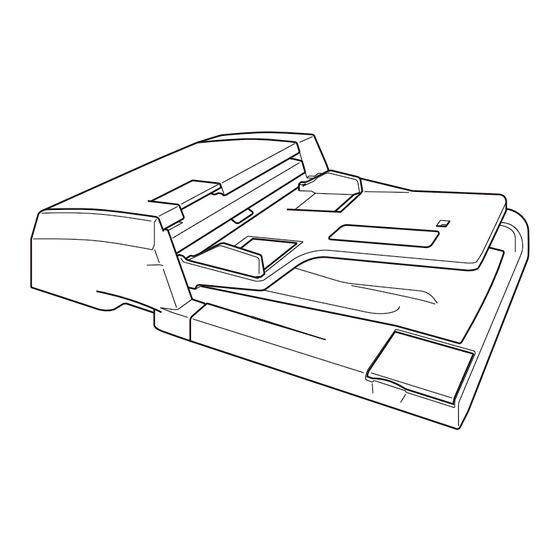
INSTALLATION GUIDE FOR THE DOCUMENT PROCESSOR
GUIDE D'INSTALLATION POUR LE PROCESSEUR DE DOCUMENT
GUIA DE INSTALACIÓN PARA EL PROCESADOR DE DOCUMENTOS
INSTALLATIONSANLEITUNG FÜR DOKUMENTENPROZESSOR
GUIDA ALL'INSTALLAZIONE DEL PROCESSORE DI DOCUMENTI
原稿自動送り装置設置手順書
DP-710
Publicité

Manuels Connexes pour Kyocera DP-710

Sommaire des Matières pour Kyocera DP-710
- Page 1 INSTALLATION GUIDE FOR THE DOCUMENT PROCESSOR GUIDE D’INSTALLATION POUR LE PROCESSEUR DE DOCUMENT GUIA DE INSTALACIÓN PARA EL PROCESADOR DE DOCUMENTOS INSTALLATIONSANLEITUNG FÜR DOKUMENTENPROZESSOR GUIDA ALL’INSTALLAZIONE DEL PROCESSORE DI DOCUMENTI 原稿自動送り装置設置手順書 DP-710...
- Page 3 E Caution label “Original face up!” Installation Procedure English (except for 100 V models) ....... 1 When installing the DP, be sure to turn the Supplied parts MFP power off and disconnect the power plug A DP............1 from the wall outlet. B Original mat ..........
- Page 4 Remove fixing tape and spacer. Install the DP. 1. Remove the fixing tape (1) from the original 4. Insert DP (A) in the MFP. feed unit cover of DP (A). 5. Place original mat (B) with its Velcro (4) facing up over the contact glass. 2.
- Page 5 Connect the signal lines. 7. Connect signal line (5) of DP (A) to the MFP and turn fixing knobs (6) at the both sides of the connecter clockwise to secure the line. Connecter les circuits de transmis- sion. 7. Connecter le circuit de transmission (5) du DP (A) au MFP et tourner les boutons de fixation (6) de chaque côté...
- Page 6 Adhere the label “Operation proce- Adhere the caution label “Remove Adhere the caution label “Original dure” (except for 100 V models) original!” (except for 100 V models) face up!” (except for 100 V models) 8. Clean the label surface of the original feed 10.
- Page 7 20mm 20mm 20mm 20mm [Operation check] 1. To check the machine operation, prepare original (a) where 4 lines (b) are drawn 20 mm from the edges of the A3 sheet and 1 line (c) is drawn at its center. 2. Connect the power plug of the MFP into the wall outlet and turn the main power on. 3.
- Page 8 Be sure to adjust in the following order. If not, the adjustment cannot be performed correctly. ● For the adjustment of DP oblique position, see page 7. <Reference value> Single copying: within ±3 mm; Duplex copying: within ±4 mm ● For the adjustment of DP original size, see page 9. <Reference value>...
- Page 9 3mm/4mm 3mm/4mm [Checking DP oblique position] 1. Check the horizontal gap between line (1) of original (a) and line (2) of copy example positions. If the gap exceeds the reference value, adjust the gap according to the following procedure. <Reference value> For single copying: The horizontal gap of line (2) should be within ±3 mm. For duplex copying: The horizontal gap of line (2) should be within ±4 mm.
- Page 10 Adjusting the DP oblique position. 2. Perform a test copy. 3. Repeat the steps above until the gap of line (2) of copy example shows 1. Turn screw (3) at the side of the right hinge and turn adjusting screw (4) the following reference values.
- Page 11 1.5% 1.5% [Checking DP original size] Adjusting DP original size. 1. Check the gap between line (1) of original (a) and line (2) of copy 1. Set the maintenance mode U070, and adjust the CONVEY SPEED example. If the gap exceeds the reference value, adjust the gap (sub-scan direction).
- Page 12 1.5% 1.5% 2. Adjust the values. 3. Perform a test copy. For the shorter length copy example (f): Increases the value. 4. Repeat the steps 1 to 3 above until the gap of line (2) of copy example For the longer length copy example (g): Decreases the value. shows the reference value.
- Page 13 2.5mm 2.5mm [Checking the DP leading edge timing] Adjusting the DP leading edge timing. 1. Check the gap between line (1) on original (a) and line (2) of copy 1. Set the maintenance mode U071, and adjust the ADJUST DATA1 example.
- Page 14 2.5mm 2.5mm 2. Adjust the values. 3. Perform a test copy. For the faster leading edge timing, copy examples (h): Decreases the 4. Repeat the steps 1 to 3 above until the gap of line (2) of copy example value. shows the reference value.
- Page 15 2mm/3mm 2mm/3mm [Checking the DP original center line] Adjusting the DP original center line. 1. Check the gap between center line (1) on original (a) and center line (2) 1. Set the maintenance mode U072, and adjust the copy example for each of single and duplex copying respectively.
- Page 16 2mm/3mm 2mm/3mm 2. Adjust the values. 3. Perform a test copy. If the center moves more front, copy example (j): Increases the value. 4. Repeat the steps 1 to 3 above until the gap of line (2) of copy example If the center moves inner, copy sample (k): Decreases the value.
- Page 17 60 1mm A(60 5mm) 128 1mm [Adjustment using the DP auto adjustment original] 1. Set maintenance mode U76 and press the START key. 2. Face F and R of the DP auto adjustment original up, and place the original from the edge where F and R are marked. Press the START key. 3.
- Page 18 MEMO...
- Page 19 MEMO...
- Page 20 2006. 2 303J956710 Rev.1.0...