Graf 350021 Notice D'installation Et D'utilisation
Table des Matières
Les langues disponibles
Les langues disponibles
Liens rapides
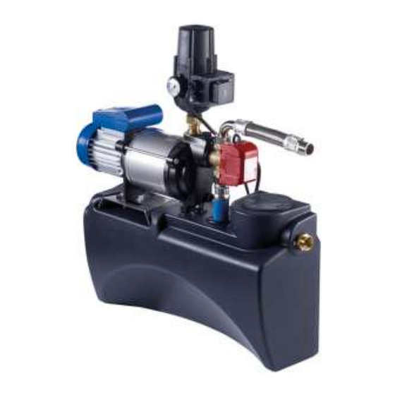
Trinkwasser-Nachspeisekonsole
Anleitung für Einbau und Wartung GRAF Trinkwasser-
DE
Nachspeisekonsole
>> Seite 1-11
Installation instructions and maintenance for the GRAF
EN
mains water back-up supply
>> Page 12-22
Notice d'installation et d'utilisation du coffret d'alimentation sur
FR
console Graf (selon norme EN1717)
>> Page 23-34
Istruzioni di installazione e manutenzione unità di controllo
IT
alimentazione acqua potabile GRAF
>> Pagina 35-45
Chapitres
Table des Matières

Manuels Connexes pour Graf 350021


Sommaire des Matières pour Graf 350021
- Page 1 Trinkwasser-Nachspeisekonsole Anleitung für Einbau und Wartung GRAF Trinkwasser- Nachspeisekonsole >> Seite 1-11 Installation instructions and maintenance for the GRAF mains water back-up supply >> Page 12-22 Notice d’installation et d’utilisation du coffret d’alimentation sur console Graf (selon norme EN1717) >> Page 23-34 Istruzioni di installazione e manutenzione unità...
- Page 25 Notice d’installation et d’utilisation du coffret d’alimentation sur console Graf (selon norme EN1717) Coffret d’alimentation Graf 15/4 Réf. 350021 Coffret d’alimentation Graf 25/4 Réf. 350022 Sommaire Afin de garantir le bon fonctionnement et la longévité de votre installation, les GÉNÉRALITÉS...
-
Page 26: Généralités
Le coffret d’alimentation doit être installé au dessus du niveau de la cuve. Le coffret d’alimentation Graf doit être placé dans un endroit sec, hors gel et bien ventilé. Les chapitres qui sui- vent vous expliquent comment effectuer l’installation et l’entretien de votre coffret d’alimentation Graf. -
Page 27: Données Techniques
3. Données techniques Dimensions et poids Poids: env. 30 kg Trop plein de sécurité selon norme EN1717 à l’arrière du bac de disconnexion Druckseite 1" AG Saugseite 1" AG Trinkwasseranschluß 3/4" AG freier Auslauf nach DIN Refoulement vers toilettes et lave-linge 1 ‘’... -
Page 28: Mise En Marche
3. Données techniques Mise en marche Le basculement eau du réseau/eau de pluie s’effectue par le biais du câble sonde se trouvant dans la cuve Vanne à flotteur Température de fonctionne- 30°C max. ment 0,3 – 4,5 bar (Dans le cas d’une pression d’eau trop élevée, utiliser un ré-... - Page 29 3. Données techniques 3.6.2 Coffret d’alimentation 25/4 Puissance absorbée 800 W Hauteur de refoulement 43 m max. Pression max. 4,3 bar Débit délivré max. 4200 l/h (voir schéma 2) Hauteur d’aspiration max. Longueur d’aspiration max. 15 m En ce qui concerne la hauteur d’aspiration en fonction de la longueur d’aspiration, voir le schéma 1.
-
Page 30: Montage Et Installation
4. Montage et installation Retirer le coffret d’alimentation de son emballage ainsi que les éléments se trouvant dans le même carton. Véri- fier que l’installation n’a subi aucun dommage durant le transport. Les dégradations doivent être signalées avant le montage. -
Page 31: Raccordement Du Trop-Plein
4. Montage et installation Raccordement du trop-plein Raccorder le trop-plein de sortie en utilisant des tuyaux PVC DN 50 disponibles dans le commerce et raccorder au réseau d’assainissement. Nous conseillons de réaliser ce trop-plein en forme de siphon à l’aide de coudes 86°. -
Page 32: Raccordement Du Tuyau De Tirage
Le tuyau d’aspiration doit être posé dans un fourreau PVC DN 100 ou DN 150 et être raccordé sur le flexible inox, sur le haut de l’électrovanne. Installer dans la cuve un kit d’aspiration ou une crépine GRAF équipé d’un clapet anti-retour. Toujours vérifier la propreté du matériel installé. Avant de poser le tuyau d’aspiration, nettoyer la gaine PVC : veiller à... -
Page 33: Branchement Du Câble Sonde
4. Montage et installation Branchement du câble sonde Brancher la prise de l’électrovanne 3 voies sur la double-prise du flotteur (voir schéma page 12). Les 20 m de câble du flotteur équipé du contrepoids jaune doivent être posés dans un fourreau PVC. Le contrepoids jaune doit être positionné... -
Page 34: Entretien Et Maintenance
5. Mise en service de l’installation Dans le cas où le remplissage du tuyau de tirage comme décrit ci-dessus est impossible, celui-ci peut aussi être rempli à partir de l’extrémité reliée au coffret d’alimentation. Pour cela, remplir le tuyau d’eau jusqu’à ce que ce dernier déborde. -
Page 35: Erreurs Frequentes Et Mesures Correctives
7. Erreurs fréquentes et mesures correctives Panne Cause Solution - Brancher la prise murale et/ou vérifier - Pas de tension la tension La pompe ne démarre pas - Faire vérifier et/ou nettoyer la pompe - Mécanisme bloqué par un spécialiste - Crépine hors de l’eau... -
Page 36: Schema De Branchement Du Coffret D'alimentation Sur Console
GRAF Iberica Tecnología del Plástico S.L. – Marquès Caldes de Montbui, 114 – ES-17003 Girona – Tel.: +34 972 913767 – Fax: +34 972 913766 GRAF UK Ltd – Target House – Thorpe Way Ind. Estate – Banbury – Oxfordshire – UK-OX16 4SP – Tel.: +44 1608 661-500 – Fax: + 44 1608 665-466...