
Manuels Connexes pour VWR International 460-0250

Sommaire des Matières pour VWR International 460-0250
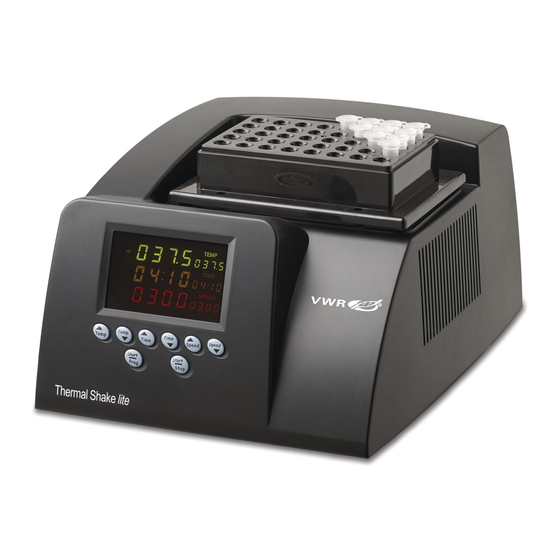
- Page 1 VWR Thermal Shake lite INSTRUCTION MANUAL UROPEAN ATALOGUE UMBER 460-0249 Thermal Shake lite, 230V ERSION : 01-2015 SSUED...
- Page 2 Legal Address of Manufacturer Europe VWR International bvba Researchpark Haasrode 2020 Geldenaaksebaan 464 B-3001 Leuven + 32 16 385011 http://be.vwr.com Country of Origin United States...
- Page 3 TABLE OF CONTENTS SECTION 1.0 INTRODUCTION SECTION 2.0 SYMBOLS AND CONVENTIONS SECTION 3.0 SAFETY PRECAUTIONS SECTION 4.0 SPECIFICATIONS SECTION 5.0 EQUIPMENT OVERVIEW SECTION 6.0 CONTROLS OVERVIEW SECTION 7.0 OPERATION GUIDE SECTION 8.0 SERVICE AND TROUBLESHOOTING SECTION 9.0 PARTS LIST SECTION 10.0 WARRANTY SECTION 11.0 EQUIPMENT DISPOSAL...
- Page 4 Section INTRODUCTION The VWR Thermal Shake lite has microprocessor controlled cooling & heating capabilities. The incubator can be equipped with various block sizes to accommodate several tube sizes and microplates. It can perform a wide range of applications including, sample storage, storage and reaction of various kinds of enzyme, DNA amplification, pre-denaturation of electrophoresis, and serum solidification.
-
Page 5: Symbols And Conventions
Section SYMBOLS AND CONVENTIONS Your VWR Thermal Shake lite uses internationally accepted graphic symbols to help convey information to the user and to call the users attention to important safety precautions and guides for using this equipment. Indicates that user should consult manual further description or discussion. Failure to heed this information may present a risk of damage or injury to persons or equipment. -
Page 6: Safety Precautions
VWR Thermal Shake lite are likely to be damaged, the rated safety level to be reduced, and the rated operation conditions to be affected. VWR International shall not be in any way responsible for the consequences resulting from operator’s not observing the following requirements. - Page 7 be replaced by a new one. The power supply should be free of heavy objects during the VWR Thermal Shake lite’s operation. Keep the power supply away from high traffic areas. Connect the A.C. Power Line While connecting or disconnecting the power line, user should insert the plug firmly to ensure good contact between the plug and socket.
-
Page 8: Normal Operating Conditions
Section SPECIFICATIONS NORMAL OPERATING CONDITIONS Ambient temperature: 10°C ~ 30°C Relative humidity Power supply AC220-240V 50/60Hz 150W Placement table-board: stable and horizontal PERFORMANCE Temperature Control Range 0 ~ 105 C Temperature Range Ambient ~ 100 C Timing Range 1 min ~ 99h59min Cooling Time From ambient to ambient -10°... -
Page 9: Basic Parameters
BASIC PARAMETERS Model Parameters 460-0250, 40 x 1.5mL 460-0251, 54 x 0.5mL 460-0252, 96 x 0.2mL 460-0253, 24 x 15mm Blocks 460-0254, Water bath (ID: 115X73X38mm) (not suggested to use when mixing function is on) 460-0255, 26 x 0.5mL and 24 x 1.5mL 460-0256, 40 x 2.0mL... -
Page 10: Equipment Overview
Section EQUIPMENT OVERVIEW This chapter describes the VWR Thermal Shake lite’s mechanical structure, keyboard and key functions, and overview before powering-on. It should be read carefully before the VWR Thermal Shake lite is first operated. Structure Description Block Case(Main Body) Display Panel and Keyboard Sticker... -
Page 11: Controls Overview
Section CONTROLS OVERVIEW Diagram of display panel Temperature increasing indicator Actual temperature indicator Constant temperature indicator Set Temperature display Temperature decreasing indicator Vibration time display Timer indicator Vibration time set up display Vibration speed indicator Vibration speed set up Button area display Vibration speed display... - Page 12 Section OPERATION GUIDE This chapter gives a through instruction to the temperature set up, vibration time set up, vibration speed set up of this instrument. It also explains how to correct the discrepancy between the actual temperature and displayed temperature, and how to set up the buzzer.
- Page 13 a) The digits of the TEMP display may be TEMP reduced or increased by pressing “ ” or “ “ respectively. TIME The digits of the TIME display may be reduced or increased by pressing “ ”or “ ” SPEE respectively.
- Page 14 Correct temperature discrepancy The temperature of the instrument has been calibrated before shipment. However, due to various conditions, there might be discrepancy between the actual temperature and displayed temperature. On such case, you may use the calibration button to correct the discrepancy.
- Page 15 c Perform the same operation again to set up the second calibration temperature such as 100 ; Note: when setting up the temperature points, an order of low temperature point first and high temperature after is recommended. If on the case high temperature point is set first and low temperature is set after, then when performing the following actual calibration,...
- Page 16 input the calibrated value and press “Short/Prog” to save it. When the calibration of 40°C is done, press TEMP “ ”to exit; at this time the calibration of 40°C is ineffective. TIME When the calibration is done for once at both 40°C and 100°C, check for the discrepancy between the two calibration points and the actual temperature points.
- Page 17 Please read the following operation instructions: a) Press both “ ”and “ ”at the same time,And the display will show On, Beep; Short Short Prog Prog b Press “ ” for once and change On to OFF; c Press “ ”and“...
-
Page 18: Troubleshooting And Repair
Section TROUBLESHOOTING AND REPAIR This chapter describes possible faults of this instrument along with instructions to the cause analysis and teaches you how to resolve the fault. Troubleshooting and Repair Problem Probable Cause Remedy Power is not Check the power and connect connected. -
Page 19: Technical Service
Problem Probable Cause Remedy Serious discrepancy between the actual Broken sensor or Contact VWR temperature and bad contact. displayed temperature. The cooling of the Thermoelectric module drastically cooling module is slows down or the broken. temperature Contact VWR cannot reach Fan is broken or below room does not work. -
Page 20: Parts List
Section PARTS LIST User replaceable accessories and spare parts Description Cat. No. L socket head wrench 460-0264 Cushioning balls for foot 460-0265 Fuse- used for 230V model 460-0266 (250V1.5A 5*20mm) - Page 21 Section WARRANTY VWR International warrants that this product will be free from defects in material and workmanship for a period of two (2) years from date of delivery. If a defect is present, VWR will, at its option and cost, repair, replace, or refund the purchase price of this product to the customer, provided it is returned during the warranty period.
-
Page 22: Equipment Disposal
EQUIPMENT DISPOSAL This equipment is marked with the crossed out wheeled bin symbol to indicate that this equipment must not be disposed of with unsorted waste. Instead it's your responsibility to correctly dispose of your equipment at lifecycle -end by handling it over to an authorized facility for separate collection and recycling. - Page 23 Fax: 044 745 13 10 Fax: (52) 470-069 Email: info@ch.vwr.com Email: info@hu.vwr.com Turkey Ireland / Northern Ireland VWR International Laboratuar Teknolojileri Ltd. ti. VWR International Ltd / Orta Mah. Cemal Gürsel Caddesi VWR International (Northern Ireland) Ltd Ördekcioglu I merkezi No.32/1 Orion Business Campus 34896 Pendik - Istanbul Tel.: +90216 598 2900...
- Page 24 VWR Thermal Shake lite BEDIENUNGSANLEITUNG UROPÄISCHE ATALOGNUMMER 460-0249 Thermal Shake lite, 230 V ERSION : 01-2015 RSTELLT...
- Page 25 Offizielle Anschrift des Herstellers Europa VWR International bvba Researchpark Haasrode 2020 Geldenaaksebaan 464 B-3001 Leuven +32-16-385011 Ursprungsland Vereinigte Staaten...
- Page 26 INHALTSVERZEICHNIS ABSCHNITT 1.0 EINLEITUNG ABSCHNITT 2.0 SYMBOLE UND KONVENTIONEN ABSCHNITT 3.0 SICHERHEITSVORKEHRUNGEN ABSCHNITT 4.0 TECHNISCHE DATEN ABSCHNITT 5.0 ÜBERBLICK ÜBER DAS GERÄT ABSCHNITT 6.0 ÜBERBLICK ÜBER DIE BEDIENELEMENTE ABSCHNITT 7.0 BETRIEBSANLEITUNG ABSCHNITT 8.0 KUNDENDIENST UND FEHLERBEHEBUNG ABSCHNITT 9.0 TEILELISTE ABSCHNITT 10.0 GARANTIE ABSCHNITT 11.0 ENTSORGUNG DES GERÄTS...
- Page 27 Abschnitt EINLEITUNG Der VWR Thermal Shake lite besitzt durch einen Mikroprozessor gesteuerte Kühl- und Aufheizfunktionen. Der Inkubator kann mit verschiedenen Blockgrößen ausgestattet werden, um mehrere Röhrchengrößen und Mikroplatten aufzunehmen. Er hat eine Vielzahl von Verwendungsmöglichkeiten wie Probenlagerung, Lagerung und Reaktion verschiedener Arten von Enzymen, DNA-Amplifikation, Vor-Denaturierung der Elektrophorese und Serumsverfestigung.
-
Page 28: Symbole Und Konventionen
Abschnitt SYMBOLE UND KONVENTIONEN Ihr VWR Thermal Shake lite verwendet international anerkannte grafische Symbole, um dem Anwender Informationen zu vermitteln und die Aufmerksamkeit des Anwenders auf wichtige Sicherheitsvorkehrungen und Anleitungen zur Benutzung dieses Geräts zu lenken. Weist darauf hin, dass der Anwender die Bedienungsanleitung für weitere Beschreibungen oder Erläuterungen konsultieren sollte. -
Page 29: Sicherheitsvorkehrungen
Sicherheitsniveau könnte verringert werden und die eingestuften Betriebsbedingungen könnten beeinflusst werden. VWR International ist in keiner Weise für die Folgen verantwortlich, die sich aus der Nichtbeachtung der folgenden Anforderungen durch den Bediener ergeben. Dieses Gerät ist ausschließlich für den Gebrauch in Gebäuden vorgesehen. - Page 30 erlaubt) und der Nennstrom der Steckdose die vorgeschriebene Spezifikation wie unten angegeben erfüllt. Aspekte der Wechselstromleitung Als Zubehörteil des VWR Thermal Shake lite sollte das Netzteil das Standardgerät darstellen. Ist das Netzteil einmal beschädigt, darf es nicht repariert, sondern muss durch ein neues ersetzt werden.
- Page 31 zertifizierten Wartungsingenieur um Hilfe zu bitten. Flüssigkeit tritt in das Gerät ein; Gerät funktioniert nicht richtig, gibt ungewöhnliche Geräusche oder Gerüche Gerät fällt auf den Boden oder das Gehäuse wird beschädigt; Signifikante Änderungen in der Leistung des Geräts...
-
Page 32: Technische Daten
Abschnitt TECHNISCHE DATEN NORMALE BETRIEBSBEDINGUNGEN Umgebungstemperatur: 10 °C ~ 30 °C Relative Luftfeuchtigkeit: 70 % Stromversorgung: 220 - 240 V Wechselstrom, 50/60 Hz 150 W Platzierung Tischplatte: stabil und horizontal LEISTUNG Temperaturkontrollbereich 0 ~ 105 C Temperaturbereich Umgebung ~ 100 C Zeitbereich 1 min ~ 99 h 59 min Abkühlzeit... - Page 33 GRUNDLEGENDE PARAMETER Modell Parameter 460-0250, 40 x 1,5 ml 460-0251, 54 x 0,5 ml 460-0252, 96 x 0,2 ml 460-0253, 24 x 15 mm Blöcke 460-0254, Wasserbad (ID: 115 x 73 x 38 mm) (Verwendung nicht empfohlen, wenn die Mischfunktion an ist)
-
Page 34: Überblick Über Das Gerät
Abschnitt ÜBERBLICK ÜBER DAS GERÄT Dieses Kapitel beschreibt die mechanische Struktur des VWR Thermal Shake lite, die Tastatur und die Tastenfunktionen und gibt einen Überblick vor der Inbetriebnahme. Es sollte sorgfältig durchgelesen werden, bevor der VWR Thermal Shake lite das erste Mal in Betrieb genommen wird. Beschreibung der Struktur Block Gehäuse (Hauptteil) - Page 35 Abschnitt ÜBERBLICK ÜBER DIE BEDIENELEMENTE Diagramm des Anzeigefelds Indikator für steigende Temperatur Anzeige der Ist-Temperatur Indikator Indikator für gleichbleibende Temperatur Anzeige der Soll-Temperatur Indikator für sinkende Temperatur Anzeige der Vibrationszeit Anzeige der Vibrationszeiteinstellung Zeitindikator Anzeige der Vibrationsgeschwindig- Indikator für Vibrationsgeschwindigkeit keitseinstellung Bereich der Schaltflächen Anzeige der Vibrations-...
- Page 36 Abschnitt BETRIEBSANLEITUNG Diese Kapitel gibt eine umfassende Anleitung zur Temperatureinstellung, Vibrationszeiteinstellung und Vibrationsgeschwindigkeitseinstellung dieses Geräts. Es erklärt auch, wie die Diskrepanz zwischen Ist-Temperatur und angezeigter Temperatur zu korrigieren ist und wie man den Summton einstellt. Vorabüberprüfung vor Inbetriebnahme Überprüfen und bestätigen Sie vor dem Einschalten zuerst folgende Punkte: 1.
- Page 37 a) Die Ziffern der Anzeige TEMP können durch TEMP Drücken von „ “ bzw. „ “ erhöht bzw. verringert werden. TIME Die Ziffern der Anzeige TIME können durch Drücken von „ “ bzw. „ “ erhöht bzw. SPEED verringert werden. Halten Sie die oben genannten Schaltflächen länger als 3 Sekunden gedrückt, um den genauen Wert einzustellen.
- Page 38 Nachdem der Einstellungswert für die Temperatur erfolgreich gespeichert wurde, heizt das Gerät automatisch auf oder kühlt ab, um den eingestellten Temperaturpunkt zu erreichen. PULSE-Vibration Short Short Prog Prog Drücken Sie „ “, um mit der sofortigen Vibration oder kurzzeitigen Vibration zu beginnen.
- Page 39 Temp Temp a) Drücken Sie gleichzeitig „ “ und Temp Temp „ “ und die Anzeige zeigt den eingestellten Wert des letzten Mals an zum Beispiel 20 und den Cursor des ersten Kalibrierungspunkts; C 1 b Drücken Sie die Schaltfläche zur Temperatureinstellung Temp Temp...
- Page 40 Temp Temp TEMP Drücken Sie gleichzeitig „ “ und Temp Temp TIME „ “, um mit der Kalibrierung zu beginnen. Die Anzeige zeigt 40.0 an und die Temperatur des Geräts erhöht sich automatisch auf 40 °C. Ist die Temperatur dann konstant, beginnt die Zeitmessung. Drücken Sie 30 Minuten später einmal auf Short Short...
- Page 41 Kalibrierung von 40 °C nicht aktiviert. Wenn die Kalibrierung einmal für 40 °C und TEMP einmal für 100 °C stattgefunden hat, überprüfen Sie die Diskrepanz zwischen den TIME beiden Kalibrierungspunkten und den Ist- Temperaturpunkten. Diese sollte sich innerhalb von 0,5 °C befinden. Sollte sie sich auf mehr als 0,5 °C belaufen, befolgen Sie bitte die oben aufgeführte Anleitung und rekalibrieren Sie, bis diese Anforderung erfüllt...
- Page 42 Short Short Prog Prog Drücken Sie einmal „ “ und ändern Sie „On“ (An) auf „OFF“ (Aus); Speed Speed Drücken Sie gleichzeitig „ “ und Speed Speed „ “, um die Einstellung zu speichern, und der Summton bei Fehler oder Abschluss wird ausgeschaltet.
-
Page 43: Fehlerbehebung Und Reparatur
Abschnitt FEHLERBEHEBUNG UND REPARATUR Dieses Kapitel beschreibt mögliche Störungen dieses Geräts zusammen mit Anleitungen hinsichtlich der Ursachenanalyse und erklärt Ihnen, wie man die Störung beheben kann. Fehlerbehebung und Reparatur Wahrscheinliche Problem Abhilfe Ursache Der Strom ist nicht Stromanschluss überprüfen und Auf dem Monitor angeschlossen. - Page 44 Wahrscheinliche Problem Abhilfe Ursache Große Diskrepanz zwischen der Ist- Defekter Sensor oder Temperatur und der mangelhafter Kontaktieren VWR angezeigten Kontakt. Temperatur. Das Abkühlen des Moduls verlangsamt thermoelektrische Kühlmodul ist defekt. sich stark oder die Kontaktieren VWR Temperatur sinkt Der Lüfter ist defekt nicht unter oder funktioniert Raumtemperatur ab.
- Page 45 Abschnitt TEILELISTE Vom Anwender auswechselbare Zubehör- und Ersatzteile Beschreibung Kat.-Nr. L-Inbusschlüssel 460-0264 Polsterballen für Fußteil 460-0265 Sicherung – verwendet für 460-0266 230-V-Modell (250 V 1,5 A 5*20 mm)
-
Page 46: Garantie
Abschnitt GARANTIE VWR International garantiert, dass dieses Produkt über einen Zeitraum von zwei (2) Jahre ab Auslieferungsdatum frei von Material- und Verarbeitungsfehlern ist. Ist ein Mangel vorhanden, wird VWR nach eigenem Ermessen und auf eigene Kosten dieses Produkt reparieren, ersetzen oder dem Kunden den Kaufpreis dieses Produkts erstatten, vorausgesetzt es wird während der Garantiezeit zurückgegeben. -
Page 47: Entsorgung Des Geräts
ENTSORGUNG DES GERÄTS Dieses Gerät ist mit dem Symbol der durchgekreuzten Mülltonne gekennzeichnet. Damit wird angegeben, dass dieses Gerät nicht zusammen mit unsortierten Abfällen entsorgt werden darf. Stattdessen tragen Sie die Verantwortung, Ihr Gerät am Ende der Nutzungsdauer ordnungsgemäß zu entsorgen, indem Sie es an eine autorisierte Einrichtung zur separaten Sammlung und zum Recycling von ausgedienten Geräten übergeben. - Page 48 Fax: 044 745 13 10 Fax: (52) 470-069 Email: info@ch.vwr.com Email: info@hu.vwr.com Turkey Ireland / Northern Ireland VWR International Laboratuar Teknolojileri Ltd. ti. VWR International Ltd / Orta Mah. Cemal Gürsel Caddesi VWR International (Northern Ireland) Ltd Ördekcioglu I merkezi No.32/1 Orion Business Campus 34896 Pendik - Istanbul Tel.: +90216 598 2900...
-
Page 49: Agitateur Chauffant Vwr Thermal Shake Lite
Agitateur chauffant VWR Thermal Shake lite MANUEL D’UTILISATION EFERENCE CATALOGUE EUROPEEN 460-0249 Agitateur chauffant Thermal Shake lite, 230 V : 1 P ERSION UBLIEE : 01-2015... -
Page 50: Adresse Légale Du Fabricant
Adresse légale du fabricant Europe VWR International bvba Researchpark Haasrode 2020 Geldenaaksebaan 464 B-3001 Leuven, Belgique + 32 16 385011 http://be.vwr.com Pays d’origine États-Unis... - Page 51 TABLE DES MATIÈRES SECTION 1.0 PRÉAMBULE SECTION 2.0 SYMBOLES ET CONVENTIONS SECTION 3.0 CONSIGNES DE SÉCURITÉ SECTION 4.0 SPÉCIFICATIONS SECTION 5.0 PRÉSENTATION DE L’ÉQUIPEMENT SECTION 6.0 PRÉSENTATION DES COMMANDES SECTION 7.0 GUIDE D’UTILISATION SECTION 8.0 ENTRETIEN ET DÉPANNAGE SECTION 9.0 LISTE DES PIÈCES SECTION 10.0 GARANTIE...
- Page 52 Section PRÉAMBULE L’agitateur chauffant VWR Thermal Shake lite est doté de fonctions de refroidissement et de chauffage contrôlées par un microprocesseur. L’incubateur peut être équipé de différentes tailles de blocs pour contenir plusieurs tailles de tubes et des microplaques. Il peut être utilisé pour de nombreuses applications, dont la conservation des échantillons, la conservation et la réaction de différents types d’enzymes, l’amplification de l’acide désoxyribonucléique (ADN), la pré- dénaturation de l’électrophorèse, et la solidification du sérum.
-
Page 53: Symboles Et Conventions
Section SYMBOLES ET CONVENTIONS Votre agitateur chauffant VWR Thermal Shake lite utilise des symboles graphiques acceptés internationalement pour aider à transmettre les informations à l’utilisateur et attirer l’attention des utilisateurs sur les consignes de sécurité et les instructions importantes pour l’utilisation de cet équipement. Indique que l’utilisateur doit consulter le manuel pour obtenir des descriptions ou des informations supplémentaires. -
Page 54: Consignes De Sécurité
VWR Thermal Shake lite, de réduire le niveau de sécurité nominal et d’affecter les conditions d’utilisation nominales. VWR International ne sera en aucun cas tenu pour responsable des conséquences du non-respect par l’opérateur des exigences suivantes. Cet instrument est uniquement destiné à une utilisation en intérieur. - Page 55 Câble d’alimentation CA En tant qu’accessoire de l’agitateur chauffant VWR Thermal Shake lite, le câble d’alimentation CA doit être le matériel par défaut. Lorsque le câble d’alimentation CA est endommagé, il ne doit pas être réparé, mais doit être remplacé par un nouveau. L’alimentation ne doit pas être entravée par des objets lourds lors de l’utilisation de l’agitateur chauffant VWR Thermal Shake lite.
- Page 56 Section SPÉCIFICATIONS CONDITIONS D’UTILISATION NORMALES Température ambiante : 10 °C à ~30 °C Humidité relative 70 % Alimentation électrique : CA 220 à 240 V, 50/60 Hz, 150 W Table de mise en place : stable et horizontale PERFORMANCES Plage de contrôle de la 0 à...
-
Page 57: Paramètres De Base
PARAMÈTRES DE BASE Modèle Paramètres 460-0250, 40 x 1,5 ml 460-0251, 54 x 0,5 ml 460-0252, 96 x 0,2 ml 460-0253, 24 x 15 mm Blocs 460-0254, Bain-marie (DI : 115 X 73 X 38 mm) (utilisation non suggérée lorsque la fonction de mélange est activée) -
Page 58: Présentation De L'équipement
Section PRÉSENTATION DE L’ÉQUIPEMENT Ce chapitre décrit la structure mécanique, le clavier et les fonctions des touches de l’agitateur chauffant VWR Thermal Shake lite, ainsi que sa présentation avant sa mise sous tension. Il doit être lu attentivement avant d’utiliser l’agitateur chauffant VWR Thermal Shake lite pour la première fois. -
Page 59: Présentation Des Commandes
Section PRÉSENTATION DES COMMANDES Schéma du panneau d’affichage Affichage de la température Indicateur d’augmentation de la température réelle Indicateur de température constante Affichage de la température programmée Indicateur de diminution de la température Affichage de la durée de vibration Indicateur de temporisation Affichage du réglage de la durée de vibration Indicateur de vitesse de vibration... - Page 60 Section GUIDE D’UTILISATION Ce chapitre donne des instructions détaillées concernant le réglage de la température, de la durée de vibration et de la vitesse de vibration de cet instrument. Il explique également comment corriger les écarts entre la température réelle et la température affichée et comment régler le signal sonore.
- Page 61 a) Vous pouvez réduire ou augmenter les caractères de l’affichage TEMP en appuyant respectivement sur la touche « » TIME (DURÉE) ou « ». SPEED (VITESSE) Vous pouvez réduire ou augmenter les caractères de l’affichage TIME (DURÉE) en appuyant respectivement sur la touche «...
- Page 62 Lorsque le réglage est terminé, appuyez sur la touche « » pour commencer le le mélange. Une fois l’enregistrement de la valeur de réglage de la température terminé, l’appareil chauffera ou refroidira automatiquement pour parvenir au point de réglage de la température. Vibration par IMPULSIONS Appuyez sur la touche «...
- Page 63 Lisez les instructions d’utilisation suivantes : a) Appuyez simultanément sur les touches « » et « », et l’affichage indiquera la indiquera la dernière valeur de réglage par exemple, 20 °C et le curseur du premier point d’étalonnage ; C 1 ; b Appuyez sur la touche de réglage de la température «...
- Page 64 Appuyez simultanément sur les touches « » et « » pour commencer commencer l’étalonnage. L’affichage indiquera 40,0 et la température de l’instrument augmentera automatiquement jusqu’à 40 °C. Une fois que la température reste constante, la temporisation commence. 30 minutes plus tard, appuyez une fois sur la touche «...
- Page 65 « » pour quitter ; à ce moment-là, l’étalonnage l’étalonnage de la température de 40 °C est sans effet. Une fois l’étalonnage terminé pour les températures de 40 °C et 100 °C, vérifiez l’écart entre les deux points d’étalonnage et les points de température réels.
- Page 66 l’affichage indiquera On (Marche) et émettra un signal (bip) ; Appuyez une fois sur la touche « » et passez de On (Marche) à Off (Arrêt) ; Appuyez simultanément sur les touches « » et « » pour enregistrer le enregistrer le paramètre, et la vibration de faible amplitude sera désactivée lors de la survenue d’une panne ou à...
-
Page 67: Dépannage Et Réparation
Section DÉPANNAGE ET RÉPARATION Ce chapitre décrit les pannes potentielles de cet instrument et fournit des instructions pour vous permettre d’analyser les causes et d’apprendre à y remédier. Dépannage et réparation N° Problème Cause probable Mesure corrective L’alimentation n’est Vérifiez l’alimentation et pas connectée. - Page 68 N° Problème Cause probable Mesure corrective Écart important entre la température réelle Capteur cassé ou Contactez VWR et la température mauvais contact. affichée. Le refroidissement Le module de du module ralentit refroidissement considérablement ou thermoélectrique est la température ne cassé. Contactez VWR peut pas descendre Le ventilateur est...
-
Page 69: Liste Des Pièces
Section LISTE DES PIÈCES Accessoires et pièces détachées à remplacer par l’utilisateur Description Réf. n° Clé en L à tête creuse 460-0264 Balles d’amortissement pour pied 460-0265 Fusible utilisé pour le modèle 230 V 460-0266 (250 V, 1,5 A, 5 x 20 mm) - Page 70 Section GARANTIE VWR International garantit que ce produit sera exempt de défauts matériels et de fabrication pendant une période de deux (2) an à compter de la date de livraison. Si un défaut est constaté, VWR procédera, à son entière discrétion et à ses frais, au remplacement, à...
-
Page 71: Mise Au Rebut De L'équipement
MISE AU REBUT DE L’ÉQUIPEMENT Cet équipement est marqué du symbole de la poubelle barrée d’une croix qui indique qu’il ne doit pas être mis au rebut avec les déchets non triés. Vous êtes responsable de la mise au rebut appropriée de cet équipement à la fin de son cycle de vie et vous devez le déposer sur un site autorisé... - Page 72 Fax: 044 745 13 10 Fax: (52) 470-069 Email: info@ch.vwr.com Email: info@hu.vwr.com Turkey Ireland / Northern Ireland VWR International Laboratuar Teknolojileri Ltd. ti. VWR International Ltd / Orta Mah. Cemal Gürsel Caddesi VWR International (Northern Ireland) Ltd Ördekcioglu I merkezi No.32/1 Orion Business Campus 34896 Pendik - Istanbul Tel.: +90216 598 2900...
- Page 73 Agitadora térmica VWR lite MANUAL DE INSTRUCCIONES ÚMERO DE CATÁLOGO EUROPEO 460-0249 Agitadora térmica lite, 230 V ERSIÓN : 01-2015 UBLICADO...
- Page 74 Dirección legal del fabricante Europa VWR International bvba Researchpark Haasrode 2020 Geldenaaksebaan 464 B-3001 Leuven + 32 16 385011 País de origen Estados Unidos...
- Page 75 ÍNDICE SECCIÓN 1.0 INTRODUCCIÓN SECCIÓN 2.0 SÍMBOLOS Y CONVENCIONES SECCIÓN 3.0 PRECAUCIONES DE SEGURIDAD SECCIÓN 4.0 ESPECIFICACIONES SECCIÓN 5.0 DESCRIPCIÓN GENERAL DEL EQUIPO SECCIÓN 6.0 DESCRIPCIÓN GENERAL CONTROLES SECCIÓN 7.0 GUÍA DE USO SECCIÓN 8.0 SERVICIO TÉCNICO Y SOLUCIÓN DE PROBLEMAS SECCIÓN 9.0 LISTA DE PIEZAS...
- Page 76 Sección INTRODUCCIÓN La agitadora térmica VWR lite dispone de capacidades de calentamiento y refrigeración controladas mediante microprocesador. La incubadora puede equiparse con varios tamaños de bloques para dar cabida a varios tamaños de tubos y microplacas. Puede realizar una gran variedad de aplicaciones, como almacenar muestras, almacenar y promover la reacción de diferentes tipos de enzimas, amplificar ADN, predesnaturalizar en electroforesis y solidificar suero.
-
Page 77: Símbolos Y Convenciones
Sección SÍMBOLOS Y CONVENCIONES La agitadora térmica VWR lite utiliza símbolos gráficos aceptados internacionalmente para transmitir información al usuario y llamar la atención de este sobre las precauciones de seguridad y las directrices importantes para el uso de este equipo. Indica que el usuario debe consultar el manual para obtener una descripción o información más detalladas. -
Page 78: Precauciones De Seguridad
VWR International no será responsable en modo alguno de las consecuencias de que el usuario no siga los requisitos indicados a continuación. Este instrumento solo está diseñado para uso en el interior. - Page 79 Consideraciones sobre el cable de CA Como accesorio de la , la fuente de alimentación de CA deberá agitadora térmica VWR lite ser el dispositivo predeterminado. Una vez dañado, el cable de CA no podrá repararse y deberá sustituirse por uno nuevo. La fuente de alimentación deberá estar libre de objetos pesados durante el funcionamiento de la .
- Page 80 Si ocurre uno de los acontecimientos siguientes, el usuario deberá desconectar el cable de alimentación de la red y ponerse en contacto con el distribuidor o preguntar a un ingeniero de mantenimiento certificado para obtener ayuda. Entra líquido en el dispositivo. El dispositivo funciona mal y emite un sonido u olor anómalo.
-
Page 81: Condiciones De Transporte Y Almacenamiento
Sección ESPECIFICACIONES CONDICIONES DE FUNCIONAMIENTO NORMAL Temperatura ambiente: 10-30 °C Humedad relativa: 70 % Fuente de alimentación: 220-240 V de CA, 50/60 Hz, 150 W Colocación en superficie estable y en horizontal rígida: RENDIMIENTO Intervalo de control de 0-105 C temperatura Intervalo de temperatura Ambiente-100 C... -
Page 82: Parámetros Básicos
PARÁMETROS BÁSICOS Modelo Parámetros 460-0250, 40 x 1,5 ml 460-0251, 54 x 0,5 ml 460-0252, 96 x 0,2 ml 460-0253, 24 x 15 mm Bloques 460-0254, baño de agua (ID: 115 X 73 X 38 mm) (no se recomienda su uso cuando la función de mezcla está... -
Page 83: Descripción General Del Equipo
Sección DESCRIPCIÓN GENERAL DEL EQUIPO Este capítulo describe la estructura mecánica, el teclado y las funciones clave de la agitadora térmica VWR lite, y proporciona una descripción general antes del encendido. Debe leerse cuidadosamente antes de utilizar la agitadora térmica VWR lite por primera vez. - Page 84 Sección DESCRIPCIÓN GENERAL CONTROLES Diagrama del panel de pantallas Pantalla de la temperatura real Indicador de aumento de temperatura Indicador Indicador de temperatura constante Pantalla de la temperatura establecida Indicador de descenso de temperatura Pantalla del tiempo de vibración Indicador de temporizador Pantalla de configuración del tiempo de Indicador de velocidad de vibración Pantalla de la velocidad de vibración configurada...
- Page 85 Sección GUÍA DE USO Este capítulo proporciona instrucciones completas sobre la configuración de la temperatura, del tiempo de vibración y de la velocidad de vibración de este instrumento. También explica cómo corregir la discrepancia entre la temperatura real y la temperatura visualizada, y cómo configurar la alarma.
- Page 86 a) Los dígitos de TEMP. pueden reducirse o TEMP. aumentarse pulsando “ ” o “ ”, respectivamente. TIEM. Los dígitos de TIEM. pueden reducirse o aumentarse pulsando “ ” o “ ”, VEL. respectivamente. Pulse los botones anteriormente mencionados durante más de tres segundos para configurar el valor exacto.
- Page 87 Vibración PUNTUAL Pulse “ “ para iniciar la vibración instantánea o la vibración a corto plazo. Pulse el botón para iniciarla y suéltelo para detenerla. La velocidad de ejecución de la vibración puntual será la velocidad de vibración más alta. Corrección de la discrepancia de temperaturas La temperatura del instrumento se ha calibrado antes del envío.
- Page 88 b) Pulse el botón de configuración de la temperatura “ ” o “ ” para configurar la primera temperatura de calibración en 40 °C. c) Realice de nuevo la misma operación para configurar la segunda temperatura de calibración como 100 Nota: Cuando configure los puntos de temperatura, se recomienda empezar por la más baja y seguir con la más alta.
- Page 89 después, pulse “ ” una vez y la pantalla mostrará “TEMP.” de forma intermitente. En este momento, la pantalla mostrará la lectura de temperatura real del termómetro. Por ejemplo, si el termómetro indica 40,5 °C, puede ajustar la pantalla de la temperatura a 40,5 °C pulsando el TEMP.
- Page 90 Configuración de la alarma A Cuando se produzca un fallo o finalice, el instrumento empezará a emitir un sonido “DI, DI, …”. Si no necesita esta función, puede deshabilitarla. Sin embargo, la configuración predeterminada es tenerla activada. B Este instrumento tiene un pitido de teclado; si pulsa el botón, sonará “DI”. Si no necesita esta función, puede deshabilitarla.
- Page 91 “Si desea salir durante la configuración, pulse “ ” y la configuración se cancelará.
-
Page 92: Solución De Problemas Yreparación
Sección SOLUCIÓN DE PROBLEMAS Y REPARACIÓN Este capítulo describe los posibles fallos de este instrumento con instrucciones sobre el análisis de la causa e indica cómo resolver el fallo. Solución de problemas y reparación N.º Problema Causa probable Solución La alimentación no Compruebe la alimentación y está... -
Page 93: Servicio Técnico
N.º Problema Causa probable Solución Compruebe el cable de El sistema no alimentación para asegurarse Puesta a tierra funciona después de que la puesta a tierra es incorrecta de la de cambiar el fiable. Recuerde desactivar la máquina. bloque. alimentación al cambiar el bloque. - Page 94 productos relacionados. • Ver información adicional sobre los productos y ofertas especiales. Contacte con nosotros Para obtener información o asistencia técnica, póngase en contacto con el representante local de VWR o visite. www.vwr.com.
-
Page 95: Lista De Piezas
Sección LISTA DE PIEZAS Accesorios y piezas de repuesto reemplazables Descripción N.º cat. Llave Allen con cabeza 460-0264 hueca Bolas amortiguadoras para 460-0265 las patas Fusible en el modelo de 460-0266 230 V (250 V 1,5 A 5 x 20 mm) - Page 96 Sección GARANTÍA VWR International garantiza que este producto estará libre de defectos tanto en los materiales como en la mano de obra durante un período de dos (2) años desde la fecha de entrega. En caso de que hubiera algún defecto, VWR, a su discreción y por su cuenta, reparará, sustituirá...
-
Page 97: Eliminación Del Equipo
ELIMINACIÓN DEL EQUIPO Este equipo está marcado con el símbolo de un contenedor de basura con ruedas tachado con una cruz para indicar que no se puede desechar con los residuos no clasificados. En su lugar, es su responsabilidad desechar el equipo correctamente al final del ciclo de vida del equipo y entregarlo a una instalación autorizada para la recogida separada de los componentes y su reciclaje. - Page 98 Fax: 044 745 13 10 Fax: (52) 470-069 Email: info@ch.vwr.com Email: info@hu.vwr.com Turkey Ireland / Northern Ireland VWR International Laboratuar Teknolojileri Ltd. ti. VWR International Ltd / Orta Mah. Cemal Gürsel Caddesi VWR International (Northern Ireland) Ltd Ördekcioglu I merkezi No.32/1 Orion Business Campus 34896 Pendik - Istanbul Tel.: +90216 598 2900...
-
Page 99: Manuale D'istruzioni
VWR Thermal shake lite MANUALE D’ISTRUZIONI UMERO DI CATALOGO EUROPEO 460-0249 Thermal shake lite, 230V ERSIONE : 01-2015 ATA DI RILASCIO... - Page 100 Indirizzo sede legale del produttore Europa VWR International bvba Researchpark Haasrode 2020 Geldenaaksebaan 464 B-3001 Leuven + 32 16 385011 http://be.vwr.com Paese di origine Stati Uniti...
-
Page 101: Table Des Matières
SOMMARIO CAPITOLO 1.0 INTRODUZIONE CAPITOLO 2.0 SIMBOLI E CONVENZIONI CAPITOLO 3.0 PRECAUZIONI DI SICUREZZA CAPITOLO 4.0 SCHEDA TECNICA CAPITOLO 5.0 PANORAMICA DEGLI STRUMENTI CAPITOLO 6.0 PANORAMICA DEI CONTROLLI CAPITOLO 7.0 GUIDA ALLE OPERAZIONI CAPITOLO 8.0 MANUTENZIONE E RISOLUZIONE DEI PROBLEMI CAPITOLO 9.0 ELENCO DELLE COMPONENTI CAPITOLO 10.0... -
Page 102: Introduzione
Capitolo INTRODUZIONE L’agitatore termico VWR Thermal Shake lite ha capacità di raffreddamento e riscaldamento controllate da un microprocessore. L’incubatore può essere equipaggiato con blocchi di varie dimensioni adatti all’inserimento di tubi e micropiastre di varie dimensioni. È in grado di eseguire un’ampia gamma di applicazioni, comprese conservazione di campioni, conservazione e reazione di vari tipi di enzimi, amplificazione di DNA, pre-denaturazione di elettroforesi e solidificazione di siero. -
Page 103: Simboli E Convenzioni
Capitolo SIMBOLI E CONVENZIONI Il vostro VWR Thermal Shake lite usa simboli grafici internazionali per facilitare la comunicazione delle informazioni all’utente e richiamare l’’attenzione dell’utente su precauzioni di sicurezza importanti e linee guida nell’uso di questo apparecchio. Indica che l’utente dovrebbe consultare il manuale per ulteriori descrizioni o spiegazioni. -
Page 104: Avvertenze Di Sicurezza
La VWR International non sarà in alcun modo responsabile delle conseguenze risultanti dalla mancata osservazione dei requisiti seguenti da parte dell’operatore. Questo apparecchio è destinato solo per uso al chiuso. - Page 105 Considerazioni sulla rete di corrente alternata (A.C.) Il dispositivo predefinito dovrebbe essere l’alimentatore A.C. accessorio del VWR Thermal Shake lite. Non si dovrebbe riparare la linea elettrica se è danneggiata ma dovrebbe essere sostituita con una nuova. Durante le operazioni del VWR Thermal Shake lite, alimentatore dovrebbe essere tenuto libero da oggetti pesanti.
-
Page 106: Scheda Tecnica
Capitolo SCHEDA TECNICA CONDIZIONI OPERATIVE NORMALI Temperatura ambiente: 10°C ~ 30°C Umidità relativa: Alimentazione: A.C. 220-240 V 50/60 Hz 150 W Posizionamento sul tavolo di stabile ed orizzontale lavoro: PRESTAZIONI Raggio di controllo della 0 ~ 105 C temperatura Gamma di temperatura Ambiente ~ 100 C Gamma di durata di tempo 1 min ~ 99 h 59 min... - Page 107 PARAMETRI BASE Modello Parametri 460-0250; 40 x 1,5 ml 460-0251; 54 x 0,5 ml 460-0252; 96 x 0,2 ml 460-0253; 24 x 15 mm Blocchi 460-0254, bagno termostatico (ID: 115 x 73 x 38 mm (si suggerire di non usarlo quando la funzione mescolamento è in funzione) 460-0255;...
-
Page 108: Panoramica Degli Strumenti
Capitolo PANORAMICA DEGLI STRUMENTI Questo capitolo descrive la struttura meccanica del VWR Thermal Shakelite, la tastiera, i tasti di funzione e la panoramica prima dell’accensione. Si raccomanda di leggerlo attentamente prima di mettere in operazione il VWR Thermal Shake lite per la prima volta. -
Page 109: Panoramica Dei Controlli
Capitolo PANORAMICA DEI CONTROLLI Diagramma del pannello per display Indicatore di aumento di temperatura Display di temperatura reale indicatore Indicatore di temperatura costante Display di temperatura predisposta Indicatore di diminuzione di temperatura Display di durata di vibrazione Indicatore di durata di Display della predisposizione di tempo durata di vibrazione... -
Page 110: Guida Alle Operazioni
Capitolo GUIDA ALLE OPERAZIONI Questo capitolo dà istruzioni complete su come predisporre la temperatura, la durata di vibrazione e la rapidità di vibrazione di questo strumento. Spiega anche come correggere la discrepanza fra la temperatura reale e quella esposta e come predisporre la suoneria. - Page 111 a) Le cifre di temperatura del display possono TEMP essere aumentate o diminuite premendo rispettivamente “ ” o “ “. TIME (DURATA) Le cifre di durata del display possono essere aumentate o diminuite premendo SPEED (VELOCITÀ) rispettivamente “ ” o “ “.
- Page 112 Vibrazione ad IMPULSI Short Short Prog Prog Premere “ ” per avviare la vibrazione istantanea o la vibrazione a breve termine. Premere il pulsante per avviarla e rilasciarlo per arrestarla. La velocità di vibrazione ad impulsi in operazione è la rapidità di vibrazione più alta. Correzione del divario in temperature La temperatura dello strumento è...
- Page 113 b Premere il pulsante di predisposizione di Temp Temp Temp Temp temperatura “ ”or “ ” per impostare il primo punto di taratura di temperatura, come per esempio 40°C. c) Eseguire nuovamente la stessa operazione per impostare la seconda temperatura di taratura come per esempio 100 ;...
- Page 114 Short Short Prog Prog minuti dopo, premere “ ” una volta sola, ed il display indicherà “TEMP.” lampeggiante. A questo punto, il display indicherà la temperatura realmente letta al TEMP termometro. Ad esempio, se al termometro si legge 40,5°C, si può TIME (DURATA) cambiare 40,5°C la temperatura indicata dal display premendo il tasto di...
- Page 115 Impostare la suoneria A Quando raggiunge la fine o quando si verifica un errore di sistema, lo strumento emetterà un suono “DI, DI…”. Se questa funzione non è richiesta la si può disattivare. Tuttavia, lo strumento è predisposto ad averla attivata. B Questo strumento ha una tastiera col bip;...
- Page 116 Speed Speed d) Poi premere entrambi “ ” e Speed Speed “ ” contemporaneamente per salvare l’impostazione, ed il bip della tastiera sarà disattivato. Per uscire durante l’impostazione, si può Start Start Stop Stop premere “ ”, e l’impostazione sarà resa inefficace.
- Page 117 Capitolo RISOLUZIONE DEI PROBLEMI E RIPARAZIONI Questo capitolo descrive i possibili guasti di questo strumento insieme alle istruzioni per analizzare le cause, ed insegna come rimediare ai guasti. Risoluzione dei problemi e riparazioni Problema Causa probabile Rimedio Alimentazione non Controllare l’alimentazione e collegata.
-
Page 118: Assistenza Tecnica
Problema Causa probabile Rimedio Discrepanza notevole tra Sensore guasto o temperatura reale e Contattare VWR cattivo contatto. temperatura indicata. Il raffreddamento del Guasto al modulo di modulo rallenta raffreddamento drasticamente e non termoelettrico. Contattare VWR arriva al di sotto Ventola guasta o non della temperatura operativa. -
Page 119: Elenco Delle Componenti
Capitolo ELENCO DELLE COMPONENTI Accessori e pezzi di ricambio sostituibili dall’utente Descrizione Cat. n. Chiave a testa esagonale L 460-0264 Sfere imbottite per piedini 460-0265 Fusibile usato per modello a 460-0266 230 V (250 V; 1,5 A; 5*20... -
Page 120: Garanzia
Capitolo Garanzia VWR International garantisce che questo prodotto sarà privo di difetti nei materiali e nella produzione per un periodo di due (2) anni dalla data di consegna. Se si presentasse un difetto, VWR, a proprie spese e a propria scelta, riparerà, sostituirà, o rimborserà... - Page 121 SMALTIMENTO DELLA STRUMENTAZIONE In questa strumentazione è presente il simbolo del cestino sbarrato da una croce che indica che non deve essere smaltito come rifiuto indifferenziato. Al contrario è vostra responsabilità smaltire correttamente la strumentazione al termine del suo ciclo di vita consegnandolo a un impianto autorizzato alla raccolta differenziata e al riciclo.
- Page 122 Fax: 044 745 13 10 Fax: (52) 470-069 Email: info@ch.vwr.com Email: info@hu.vwr.com Turkey Ireland / Northern Ireland VWR International Laboratuar Teknolojileri Ltd. ti. VWR International Ltd / Orta Mah. Cemal Gürsel Caddesi VWR International (Northern Ireland) Ltd Ördekcioglu I merkezi No.32/1 Orion Business Campus 34896 Pendik - Istanbul Tel.: +90216 598 2900...