Publicité
Liens rapides
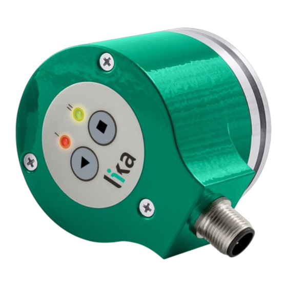
ROTACOD
Absolute encoders
EMC58 TA • EMC59 TA • EMC60 TA
Series
Complete documentation
available for download at www.lika.biz
Warning: encoders having order code ending with "/Sxxx" may have mechanical and electrical characteristics different from standard and be supplied with additional documentation for special connections (Technical Info).
Attenzione: gli encoder con codice di ordinazione finale "/Sxxx" possono avere caratteristiche meccaniche ed elettriche diverse dallo standard ed essere provvisti di documentazione aggiuntiva per cablaggi speciali (Technical info).
Achtung: Geräte, deren Bestellschlüssel mit der Kennung /Sxxx enden, können in ihren mech. und elektr. Eigenschaften vom Standard abweichen. Diese werden daher mit einer ergänzenden Dokumentation ausgeliefert (Technical info).
Atención: los encoders con código de pedido acabado en "/Sxxx" pueden tener caracteristicas mecánicas y eléctricas diferentes a las basicas y documentación adicional relativa a conexiones especiales (Technical Info).
Attention: les codeurs avec code de commande terminant en "/Sxxx" peuvent avoir des caractéristiques mécaniques et électriques différentes du standard et documentation additionnelle pour les câblages spéciaux (Technical info).
EN
Mounting instructions
x58:
Fasten the anti-rotation pin 1 to the rear of the motor (secure it
using a locknut);
fix the tempered pin 6 to the rear of the motor;
x60:
mount the encoder on the motor shaft using the reducing sleeve 8 (if
supplied). Avoid forcing the encoder shaft;
x58:
insert the anti-rotation pin 1 into the slot on the flange of the
encoder; this secures it in place by grub screw 2, preset at Lika;
x59:
fasten the fixing plate 4 to the rear of the motor using two M3
cylindrical head screws 5;
x60:
make sure the anti-rotation pin 6 is inserted properly into the
fixing plate 7;
fix the collar 3 to the encoder shaft.
ES
Instrucciones de montaje
x58:
Fijar el pin antigiro 1 en la parte posterior del motor (fijación
mediante contratuerca);
fijar el pasador temprado 6 detrás del motor;
x60:
montar el encoder y el manguito reductor 8 (si se suministra) en el eje del
motor sin forzar el eje del encoder;
x58:
insertar el pin antigiro 1 en el fresado de la brida del encoder; de
esta manera el pin 1 es mantenido en su posición mediante el
tornillo 2 prefijado por Lika;
x59:
fijar la placa de fijación 4 en la parte posterior del motor
mediante los dos tornillos 5 de cabeza cilíndrica tipo M3;
x60:
asegurarse de que el pin antigiro 6 queda insertado en la placa de
fijación 7;
fijar el collar 3 de el eje encoder.
EMC58
Electrical connection
Description
Cable A8
M12 5-pin
+Iout / +Vout
Brown
1
+13Vdc +30Vdc
Red
2
0VDC
Black
3
START
Pink
4
STOP
Green
5
Analogue 0V
White
-
FAULT
Blue
-
Shield
Shield
Case
+Iout = analogue current output
START and STOP inputs = the same as
+Vout = analogue voltage output
the START / STOP keys; they are
Fault = error signal for cable
active at HIGH logic level (voltage
integrity check (current outputs only)
greater than 10V must be applied).
Installation has to be carried out with power supply disconnected.
L'installazione deve essere eseguita in assenza di tensione.
Der Anschluss darf nur bei ausgeschalteter Versorgungsspannung erfolgen.
La instalación sólo debe ser efectuada en ausencia total de tensión.
Le montage du dispositif doit être effectué en absence totale de tension.
IT
x58:
Fissare il pin antirotazione 1 sul retro del motore (fissaggio con
controdado);
fissare la spina temprata 6 sul retro del motore;
x60:
inserire l'encoder sull'albero del motore utilizzando la boccola di riduzione 8 (se
fornita). Evitare sforzi sull'albero encoder;
x58:
inserire il pin antirotazione 1 nella fresatura della flangia encoder;
esso rimane così in posizione grazie al grano 2 prefissato da Lika;
x59:
fissare la molla di fissaggio 4 sul retro del motore utilizzando due
viti M3 a testa cilindrica 5;
x60:
assicurarsi che il pin antirotazione 6 sia inserito nella molla di
fissaggio 7;
fissare il collare 3 dell'albero encoder.
FR
x58:
Fixer le pivot antirotation 1 à la partie postérieure du moteur (le
bloquer avec un contre-écrou);
fixer la goupille durcie 6 à la partie postérieure du moteur;
x60:
monter le codeur et la douille de réduction 8 (si fournie) sur l'arbre moteur sans
forcer l'arbre du codeur;
x58:
introduire le pivot antirotation 1 à l'intérieur de la fraisage dans la
bride du codeur; de cette façon le pivot 1 est maintenu en position
par le boulon sans tête 2 préfixé par Lika;
x59:
fixer la plaquette de fixation 4 à la partie postérieure du moteur en
utilisant deux vis type M3 à tête cylindrique 5;
x60:
s'assurer que le pivot antirotation 6 soit inséré sur la plaquette de
fixation 7;
fixer le collier 3 de l'arbre codeur.
EMC59
M12 5-pin
Connector type
Male, A coding
frontal side
lato contatti
Aufsicht Stiftseite
lado contactos
côté contacts
Out TI1: min = 4 mA, max = 20 mA
Out TI2: min = 0 mA, max = 20 mA
Out TI3: min = 0 mA, max = 24 mA
Out TV1: min = 0 V, max = 5 V
Out TV2: min = 0 V, max = 10 V
Out TV3: min = -5 V, max = +5 V
Out TV4: min = -10 V, max = +10V
Istruzioni di montaggio
Instructions de montage
TEACH-IN procedure
• During this procedure the analogue
output is disabled;
• simultaneously press both START and
STOP keys for 5 seconds (do not
exceed 10 seconds!);
• move the axis to the start position in
the travel of your application;
• press the START key for 2 seconds;
LED I is solidly lit, LED II keeps on
blinking; exit is inhibited until process
completion;
• move the axis to the end position in the
travel of your application;
• press the STOP key for 2 seconds;
LED II is solidly lit; the output is enabled
again; releasing the keys causes the
LEDs to signal normal operation with
user settings.
DE
Montagehinweise
x58:
Antirotationspin 1 auf der Rückseite des Motors anschrauben und
durch die Verwendung einer Gegenmutter sichern;
gehärtete Stift 6 auf der Rückseite des Motors anschrauben;
x60:
Geber und Reduzierhülse 8 (wenn erforderlich) auf die Motorwelle montieren.
Belastungen der Geberwelle vermeiden;
x58:
Antirotationspin 1 im Geberflansch einstecken. Der Antirotationspin
1 behält seine Position durch den angeschraubten Gewindestift 2;
x59:
Drehmomentstütze 4 auf der Rückseite des Motors mit zwei M3
Zylinderschrauben 5 befestigen;
x60:
der gehärtete Stift 6 korrekt in die Drehmomentstütze 7 eingreifen
lassen;
Klemmflansch 3 festschrauben.
MOTOR
SHAFT
EMC58
EMC59
EMC60
EMC60
Aborting TEACH-IN
The TEACH-IN procedure can be aborted only
before setting the start position (with START
key).
To
abort
the
procedure
simultaneously press both START and STOP
keys. The unit will be restored to the
previous working condition, before starting
the TEACH-IN procedure.
Restoring the DEFAULTS
Simultaneously press both START and STOP
keys for 10 seconds. Both LEDs light up
solidly after about 5 seconds. After 10
seconds the factory default settings are
WARNING If the start position
restored, LED I switches off while LED II stays
(START ) is the same as the
lit. With default settings, the encoder is set at
end position (STOP ), the unit
the halfway point along a 16-revolution
resets
travel, position value increments by rotating
settings.
the shaft clockwise.
A [mm]
min
max
8
18
to
factory
default
Publicité

Manuels Connexes pour Lika ROTACOD EMC58 TA Série


Sommaire des Matières pour Lika ROTACOD EMC58 TA Série
- Page 1 x58: Antirotationspin 1 im Geberflansch einstecken. Der Antirotationspin encoder; this secures it in place by grub screw 2, preset at Lika; esso rimane così in posizione grazie al grano 2 prefissato da Lika; 1 behält seine Position durch den angeschraubten Gewindestift 2;...
- Page 2 Current analogue output 4 mA – 20 mA la Société Lika Electronic nie toute responsabilité pour tout dommage ou blessure que l'utilisateur peut encourir à la suite de la non- Current analogue output 0 mA – 20 mA observance des normes de sécurité.