Hitachi ATW-AOS-02 Manuel D'installation
Liens rapides
DEUTSCH
FIGURES
FRANÇAIS
Fig. 1 (Dimensional Data)
Fig. 2
1. APPLICABLE MODELS
This Auxiliary output signal box is applicable to YUTAKI indoor units for the HITACHI air to water split
systems
2. GENERAL DATA
Item
Specification
Power supply / Consumption
1~230V ±10% 50Hz / 2.3kW
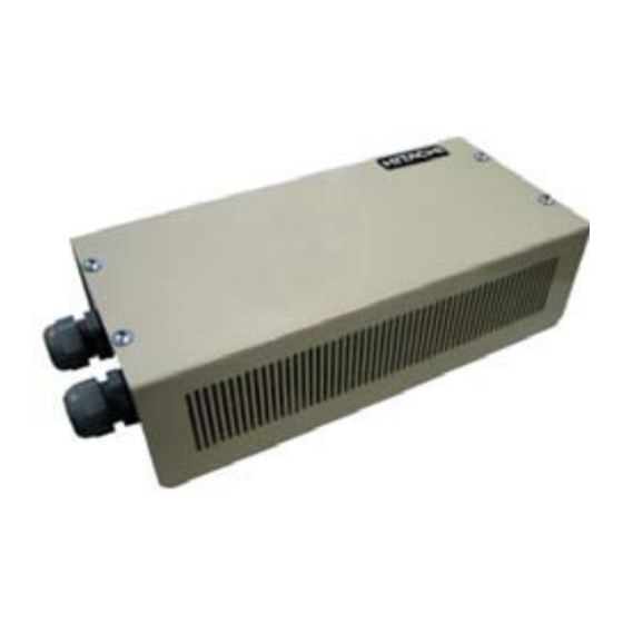
Outer dimensions / Weight
Width: 92mm, Depth: 298mm, Heigth:65.5mm / 2kg
Assembly conditions
Indoor (in a panel or desktop)
Ambient temperature / Humidity
0~40ºC / 25~85% (without condensation)
Output restrictions
V:230V AC, 5A
3. INSTALLATION
3.1. SELECTION OF INSTALLATION POSITION
Caution: Read this manual carefully before performing installation and configuration
Attention: Do no install ATW-AOS-02 in places:
-
with vapour, oil or dispersed liquids, with heat sources nearby, where accumulation,
generation or leak of inflammable gases has been detected.
Danger: Always disconnect the power supply when handling the machine, in order to avoid electrical discharges
Do not connect the interface to the power supply until the installation has been completed.
3.2. INSTALLATION PROCEDURE (FIG.1)
In case of Mounting onto the Wall:
1.
Remove the rubber supports
2.
Unscrew the 4 screws from the top cover and remove it
3.
Attach the box to the rear vertical board from the inside with M4 screws (not provided) and place 3
mm washers on the outside to separate the box from the wall.
4.
Reinstall the top cover.
4
OPERATION (FIG.2)
Output
Default configuration
Description
This signal allows activation of mechanisms that protect from and
OUT 5
Alarm signal
warn of possible failures in the unit. The signal will be enabled
when the unit is in alarm (indoor or outdoor).
This signal allows control of the machine's status at all times; it is
OUT 6
Operation signal
very useful for centralized applications. The signal will be enabled
when Thermo ON operation.
This signal allows control of the compressor's status. The signal
OUT 7
Cooling signal
will be enabled when cooling mode.
OUT 8
Demand-ON signal on circuit 1
Signal is enabled when circuit 1 is operating in Demand-ON.
5. REMARKS
-
Check to ensure that the wiring is correctly performed and follows the local regulation for the electrical
installation.
-
The contact failure may cause abnormal operation.
1. ZULÄSSIGE MODELLE
Diese Hilfsausgangssignale können für die YUTAKI Innengeräte der Luft-/Wasser-Systeme von HITACHI
verwendet werden.
2. TECHNISCHE DATEN
Element
Beschreibung
Stromversorgung / Energieverbrauch
1~230V ±10% 50Hz / 2,3 kW
Außenabmessungen / Gewicht
Breite: 92mm, Tiefe: 298mm, Höhe :65,5mm / 2kg
Montagebedingungen
Innen (in einer Tafel oder als Tischgerät)
Umgebungstemperatur / Feuchtigkeit
0~40ºC / 25~85% (ohne Kondensation)
Ausgangs-Beschränkungen
V:230V WS, 5A
3. INSTALLATION
3.1. AUSWAHL DER INSTALLATIONSPOSITION
Vorsicht: Lesen Sie dieses Handbuch vor der Installation und Konfiguration sorgfältig durch.
Achtung: Installieren Sie ATW-AOS-02 nicht an Orten...:
-
mit Dampf, Öl oder verteilten Flüssigkeiten und Wärmequellen in der Nähe, mit einer
möglichen Aufstauung, Erzeugung, oder Leckage von entzündbaren Gasen.
Gefahr: Unterbrechen Sie vor eventuellen Arbeiten am Gerät immer die Stromversorgung, um einen
.
elektrischen Schlag zu vermeiden
Schließen Sie die Schnittstelle nicht an die Stromversorgung an, solange die Installation nicht abgeschlossen ist.
3.2. INSTALLATIONSSCHRITTE (ABB. 1)
Wandmontage:
1.
Entfernen Sie die Gummifüße
2.
Lösen Sie die 4 Schrauben von der oberen Abdeckung und entfernen Sie diese.
3.
Befestigen Sie das Gehäuse mit M4-Schrauben (nicht mitgeliefert) von innen an der senkrechten
hinteren Platte und bringen Sie an der Außenseite 3mm-Unterlegscheiben an, um einen Abstand
zwischen Gehäuse und Wand zu schaffen.
4.
Montieren Sie die obere Abdeckung wieder.
4
BETRIEB (ABB. 2)
Ausgang
Standardeinstellungen
Beschreibung
Mit diesem Signal können Mechanismen aktiviert werden, die vor möglichen Störungen
AUS 5
Alarmsignal
im Gerät schützen oder warnen. Dieses Signal wird aktiviert, wenn das Gerät in
Alarmzustand ist (Innen- oder Außengerät).
Mit diesem Signal kann der Status des Geräts jederzeit gesteuert werden. Es ist sehr nützlich
AUS 6
Betriebssignal
bei zentralisierten Anwendungen. Dieses Signal wird aktiviert, wenn Thermo ON in Betrieb ist.
Mit diesem Signal kann der Status des Kompressors gesteuert werden. Dieses Signal
AUS 7
Kühlsignal
wird im Kühlbetrieb aktiviert.
Anforderungssignal ON
Das Signal wird aktiviert, wenn Kreislauf 1 in Anforderung ON ist.
AUS 8
am Kreislauf 1
5. BEMERKUNGEN
-
Vergewissern Sie sich, dass die Verkabelung korrekt ausgeführt ist und die örtlichen Richtlinien für
elektrische Installationen erfüllt.
-
Ein falscher Anschluss kann zu Betriebsstörungen führen.
INSTALLATION MANUAL
MANUAL DE INSTALACIÓN
INSTALLATIOSANLEITUNG
MANUEL D'INSTALLATION
MANUALE DI INSTALLAZIONE
Do not perform installation work without referring to our installation manual.
No realice la instalación de este equipo sin antes consultar este manual de instalación.
Bei der Installation unbedingt die Hinweise in der Installationsanleitung beachten.
Consulter notre manuel avant de réaliser une quelconque installation.
Realizzare l'installazione seguendo quanto indicato in questo manuale.
Nao inicie os trabalhos de montagem sem consultar o nosso manual de montagem.
Udfor ikke installationsarbejder uden forst at donsultere vores vejledning.
Voer geen enkele handeling uit om de apparatuur alvorens deze hadleiding te hebben doorgelezen.
Utför inte nagra installationsarbeten utan att först läsa var installationsmanual
Διαβάστε προσεκτικά το εγχειρίδιο αυτό πριν χρησιμοποιήσετε το κλιματιστικό. Κρατήστε το για μελλοντική
αναφορά
.
1. MODELOS APLICABLES
Estas señales de salida auxiliar se aplican a las unidades interiores YUTAKI de los sistemas de aire agua
ENGLISH
de HITACHI.
2. DATOS GENERALES
Elemento
Fuente de alimentación / Consumo
Dimensiones exteriores / Peso
Condiciones de montaje
Temperatura ambiente / Humedad
Restricciones de salida
3. INSTALACIÓN
3.1. SELECCIÓN DE LA POSICIÓN PARA LA INSTALACIÓN
Precaución: Lea este manual con atención antes de llevar a cabo la instalación y la configuración.
Atención: No instale el ATW-AOS-02 en lugares:
-
-con vapor, aceite o líquidos dispersos, donde haya fuentes de calor cerca, donde se
detecte generación, acumulación o fugas de gases inflamables.
.
Peligro: Desconecte siempre la fuente de alimentación cuando manipule la máquina para evitar descargas
eléctricas.
No conecte la interfaz a la fuente de alimentación hasta que haya terminado la instalación.
3.2. PROCEDIMIENTO DE INSTALACIÓN (FIG.1)
En caso de montaje en la pared:
1.
Retire los soportes de caucho
2.
Quite los 4 tornillos de la tapa superior y retírela
3.
Sujete la caja a la placa vertical posterior desde el interior con tornillos M4 (no suministrados) y
ponga arandelas de 3 mm en el exterior para separar la caja de la pared.
4.
Vuelva a colocar la tapa.
4.
FUNCIONAMIENTO (FIG.2)
Salida
Configuración por defecto
SALIDA 5
Señal de alarma
SALIDA 6
Señal de funcionamiento
SALIDA 7
Señal de enfriamiento
Señal de Demanda encendida
SALIDA 8
5. OBSERVACIONES
-
Asegúrese de que el cableado está correctamente conectado y siga las normativas locales para la
instalación eléctrica.
-
La falta de contacto puede provocar un funcionamiento anómalo.
1. MODÈLES APPLICABLES
Ce signal de sortie auxiliaire est applicable aux unités intérieures YUTAKI pour les systèmes air-eau HITACHI
2. CARACTÉRISTIQUES GÉNÉRALES
Élément
Alimentation / Consommation
Dimensions extérieures / Poids
Conditions de montage
Température ambiante / Humidité
Restrictions de sortie
DEUTSCH
3. INSTALLATION
3.1. SÉLÉCTION DE LA POSITION D'INSTALLATION
Attention : Veuillez lire ce manuel soigneusement avant de réaliser l'installation et la configuration
Attention : Ne pas installer ATW-AOS-02 à des endroits :
contenant de la vapeur, de l'huile ou des liquides déversés, proches de sources de chaleur,
-
où une accumulation, une génération ou une fuite de gaz inflammable a été détectée.
Danger: Débranchez toujours l'alimentation électrique lorsque vous manipulez la machine afin d'éviter les
.
décharges électriques
Ne connectez l'interface à l'alimentation électrique qu'une fois l'installation terminée.
3.2. PROCÉDURE D'INSTALLATION (FIG.1)
En cas de fixation murale :
1.
Retirez les supports en caoutchouc
2.
Dévissez les 4 vis du panneau supérieur et retirez-le
3.
Depuis son intérieur, fixez le boîtier à la plaque verticale arrière au moyen de vis M4 (non
fournies), et placez des rondelles de 3 mm à l'extérieur pour séparer le boîtier du mur.
4.
Réinstallez le panneau supérieur.
4
FONCTIONNEMENT (FIG.2)
Réglages par defaut
Sortie
Signal d'alarme
SORTIE 5
SORTIE 6
Signal de fonctionnement
SORTIE 7
Signal de refroidissement
Signal demand-ON pour le
SORTIE 8
5. REMARQUES
-
Vérifiez que le câblage est correctement réalisé et respectez les réglementations locales en matière
d'installations électriques.
-
Le défaut de contact peut entraîner un fonctionnement anormal.
ATW-AOS-02
MANUAL DE INSTALAÇÃO
INSTALLATIONSVEJLEDNING
INSTALLATIEHANDLEIDING
INSTALLATIONSHANDBOKEN
ΕΓΧΕΙΡΙΔΙΟ ΕΓΚΑΤΑΣΤΑΣΗΣ
PMML0417A rev.0 - 11/2015 - Printed in Spain
Especificaciones
1~230V ±10% 50Hz / 2,3 kW
Ancho: 92mm, Fondo: 298mm, Alto: 65,5mm / 2 kg
En interiores (en un panel o sobremesa)
0~40ºC / 25~85% (sin condensación)
V: 230V CA, 5A
Descripción
Esta señal permite la activación de los mecanismos de protección y
advierte de los posibles fallos en la unidad. La señal se activará
cuando haya una alarma en la unidad (interior o exterior).
Esta señal permite controlar el estado del aparato en todo momento;
es muy útil para aplicaciones centralizadas. La señal se activará
cuando funcione en condición de Thermo ON.
Esta señal permite controlar el estado del compresor. La señal se
activará en modo enfriamiento.
La señal se activará cuando el circuito 1 funcione en condición de
en el circuito 1
demanda encendida.
Spécifications
1~230V ±10% 50Hz / 2,3 kW
Largeur : 92mm, Profondeur : 298mm, Hauteur : 65,5mm / 2kg
À l'intérieur (dans un panneau ou un ordinateur de bureau)
0~40ºC / 25~85% (sans condensation)
V:230V CA, 5A
Description
Ce signal permet l'activation des mécanismes qui protègent contre
les défauts possibles de l'unité et servent d'avertissement. Le signal
sera activé lorsque l'unité est en alarme (intérieur ou extérieur)
Ce signal permet de contrôler en permanence l'état de la machine ; il
est très utile dans les dispositifs centralisés. Le signal sera activé lors
du fonctionnement du Thermo ON.
Ce signal permet le contrôle de l'état du compresseur. Le signal sera
activé en mode refroidissement.
Le signal est activé lorsque le circuit 1 fonctionne en demand-ON.
circuit 1
ENGLISH
ESPAÑOL
-
DEUTSCH
FRANÇAIS
ITALIANO
PORTUGUÊS
DANSK
NEDERLANDS
SVENSKA
E
HNIKA
ESPAÑOL
FRANÇAIS

Sommaire des Matières pour Hitachi ATW-AOS-02
- Page 1 1. APPLICABLE MODELS 1. MODELOS APLICABLES This Auxiliary output signal box is applicable to YUTAKI indoor units for the HITACHI air to water split Estas señales de salida auxiliar se aplican a las unidades interiores YUTAKI de los sistemas de aire agua...
- Page 2 1. MODELLI IDONEI 1. MODELOS APLICÁVEIS Questo segnale di output ausiliario è applicabile alle unità interne YUTAKI per i sistemi di calore aria-acqua HITACHI Este sinais de saída auxiliar destina-se às unidades interiores YUTAKI para os sistemas de ar para água HITACHI 2.