
Sommaire des Matières pour Salicru ILUEST NE Série
- Page 1 VOLTAGE DIMMER-STABILIZER ILUEST NE series. STABILISATEUR-RÉDUCTEUR DE TENSION, ILUEST série NE User’s and operating manual. Manuel d’installation et d’opération EK462D11 - 1 -...
- Page 2 - 2 -...
-
Page 3: Safety Warnings
SAFETY WARNINGS ...................... 6-8 MISES EN GARDE DE SÉCURITÉ .................. 34-36 User’s manual, installation and start up..............4-30 Manuel d’utilisateur, installation et mise en service.......... 32-58 - 3 -... - Page 31 - 31 -...
-
Page 32: Assurance De La Qualité Et Réglementation
Table des matières. 1.- INTRODUCTION 1.1.- Lettre de remerciement 1.2.- Utilisation du manuel 1.2.1.- Conventions et symboles utilisés 1.2.2.- Renseignements complémentaires et/ou assistance 2.- ASSURANCE DE LA QUALITÉ ET RÉGLEMENTATION 2.1.- Déclaration de la Direction 2.2.- Réglementation 2.3.- Sécurité et premiers secours 2.4.- Environnement 3.- PRÉSENTATION 3.1.- Vues et légendes... -
Page 33: Opération
4.6.2.- Connexion du contrôle à distance (Ordre d’économie) 4.6.3.- Connexion de la sortie 5.- OPÉRATION 5.1.- Mise en marche et arrêt 5.1.1.- Contrôles avant la mise en marche 5.1.2.- Mise en marche 5.1.3.- Arrêt complet de l’appareil 5.2.- Indications, sélecteurs et réglages des contrôles électroniques BM478* 5.2.1.- Indications par phase 5.2.2.- Sétecteurs par phase 5.2.3.- Réglages par phase... -
Page 34: Lettre De Remerciement
C’est pourquoi l’installation, la maintenance et/ou la réparation de l’appareil référencé seront obligatoirement confiées au personnel de SALICRU ou à du personnel qualifié expressément agréé. Fidèle à sa politique d’évolution constante, notre société se réserve le droit de modifier sans préavis les caractéristiques de l’appareil, en totalité... -
Page 35: Réglementation
ISO 9001 :2000 et ISO 14001 :2004 et aussi pour nos Client et Parts Intéressées. De la même manière, la Direction de SALICRU est engagé avec le développement et amélioration du Système de Gestion de la Qualité et Environnement, à travers: - La communication à... -
Page 36: Sécurité Et Premiers Secours
Recyclage de l’ILUEST à la fin de sa vie utile: SALICRU s’engage à utiliser les services de sociétés autorisées et conformes avec la réglementation pour le traitement de l’ensemble des produits récupérés à la fin de sa vie utile (nous vous prions de mettre en contact avec votre distributeur). -
Page 37: Vues Et Légendes
3.- PRÉSENTATION 3.1.- Vues et légendes 3.1.1.- Légendes des vues de l’appareil ) Borne neutre N d’entrée. Magnétothermique d’entrée phase T ) Borne phase R d’entrée. Commutateur By-pass manuel (en option) ) Borne phase S d’entrée. Programmateur horaire, ordre démarrage mode éco ) Borne phase T d’entrée. -
Page 38: Contrôle Électronique Bm478
3.1.3.- Contrôle électronique BM478* Vue du contrôle électronique BM478*. Voir explication sur les contrôles au paragraphe 5.2. CN49 CN18 1 FAN THERMAL N (remote control) SWITCH NOMINAL OUTPUT VOLTAGE POWER SUPPLY SAVING VOLTAGE CN22 LD10 LD11 Fig. 1. Vue du contrôle électronique BM478* - 38 -... -
Page 39: Définition Et Structure
3.2.- Définition et structure 3.2.1.- Nomenclature Serie ILUEST monofhasé NE 10-2ISBMD-COM "AC" I 220V 60Hz "EE84526" Appareil spécial "EE" Frequence si n'est pas 50Hz Tension si n'est pas 230Vac Interface à relais "AC" Equipement spécial avec contrôle BM158 "AC-BCN" Equipement spécial. Magnetothermique d'entrée tripolaire avec contrôle BM158 "AR"... -
Page 40: Schéma Structurel
3.2.2.- Schéma structurel Les stabilisateurs-réducteurs de flux, série ILUEST, sont fabriqués avec un transformateur compensateur ou Booster (fig. 2). By-pass By-pass manuel (en Transformateur rapport «Booster» Entrée Sortie automatique option) Autotransformateur multiprises Interrupteurs statiques d’état solide Contrôle à Démarrages distance progressifs ON/OFF saving Contrôle de... -
Page 41: Principe De Fonctionnement
Les principaux éléments constructifs sont (voir fig.2) : Autotransformateur multiprise par phase Transformateur booster par phase Contrôle électronique avec microprocesseur par phase By-pass automatique d’état solide par phase Démarrage progressif par contrôle à distance Canal de communication RS-485 Programmateur horaire de contrôle de niveau d’économie (en option) By-pass manuel (en option) Les interrupteurs statiques sont des semi-conducteurs contrôlés par un système électronique, de sorte à... -
Page 42: Bypass Automatique À Contacteurs
Un (V) 230 V 210 V VM saving level HPS saving level t t t t t 0.- 0.- 0.- 0.- 0.- Mise en marche du système 4.- 4.- 4.- 4.- 4.- Arrivée au niveau d’économie, selon le type de lampes 1.- 1.- 1.- 1.- Démarrage en «... - Page 43 3.4.2.- Bypass manuel L’ILUEST est livré avec, en option, un commutateur de bypass manuel à 2 positions, qui permet de sélectionner l’alimentation de sortie soit directement du réseau commercial (position 1), , , , , soit de l’ILUEST (position 2). Si l’ILUEST incorpore cette option, il est livré...
-
Page 44: Instructions De Sécurité Importantes
4.- INSTALLATION 4.1.- Instructions de sécurité importantes • Réviser les « Instructions de sécurité » (voir document EK266*08). • Vérifier que les données de la plaque des caractéristiques correspondent aux données requises pour l’installation. • Les deux versions de l’ILUEST disposent de 4 trous pour pouvoir les fixer sur un socle solide nivelé, afin d’immobiliser l’appareil. Il faut réaliser cette opération mécanique avant de poursuivre l’installation. - Page 45 Housse en plastique Documentation (Manuel d’installation et d’opération) Carton inférieur Palette en bois 4 protections d’angle EPS. 2 plaques latérales EPS. Emballage carton 4 cerclages polyester 8 éléments de guidage pour cerclage Étiquette emballage Carton supérieur Figures 4 à 9. Déballage - 45 -...
-
Page 46: Emplacement
• L’emballage de l’appareil comprend une palette en bois, un habillage en carton ou en bois selon les cas, des protections d’angle en polyéthylène expansé (EPS) ou en mousse de polyéthylène (PE), une housse en polyéthylène et un cerclage en polyester. Tous les matériaux étant recyclables, prière de respecter la réglementation en vigueur si vous devez les jeter. Nous recommandons de conserver l’emballage, car vous pourriez en avoir besoin plus tard. -
Page 47: Ports De Communication
4.4.- Ports de communication L’ILUEST dispose de 3 ports série RS485, un par phase, pour le branchement des éléments optionnels : • Display LCD • La carte Pack télégestion • La carte de communications étendues 4.5.- Organes de protection et sections de câbles recommandées 4.5.1.- Protections recommandées Installer les protections contre les surintensités (surcharges et courts-circuits), contre les courants de défaut à... - Page 48 Ligne de liaison Sonde lumineuse Contacteur de mise en marche du système Stabilisateur- Horloge astronomique ou réducteur de programmateur horaire tension ILUEST Interrupteur contrôle manuel SORTIE 1 SORTIE 2 SORTIE 3 Lignes de distribution éclairage Fig. 11. Schéma des branchements sur une installation type triphasée, munie d’un stabilisateur-réducteur de tension ILUEST. - 48 -...
-
Page 49: Connexion Du Contrôle À Distance (Ordre D'économie)
4.6.2.- Connexion du contrôle à distance (ordre d’économie) • Indépendamment de la structure, de la version et de la puissance de l’appareil, pour les branchements, nous disposons de trois groupes de deux bornes, destinés au contrôle à distance ou à l’ordre d’économie, étiquetés sur l’appareil comme «Remote Control». -
Page 50: Mise En Marche Et Arrêt
5.- OPÉRATION 5.1.- Mise en marche et arrêt 5.1.1.- Contrôles avant la mise en marche Avant de procéder à la mise en marche du système, il convient de faire quelques réglages et de procéder à des vérifications: • Vérifier la correcte connexion de l’alimentation à l’appareil et aux charges, conformément aux procédures décrites au chapitre précédent. -
Page 51: Indications Par Phase
5.2.- Indications, sélecteurs et réglages des contrôles électroniques BM478* Sur la figure 1 du paragraphe 3.1.3. nous pouvons voir la disposition des différents indicateurs. 5.2.1.- Indications par phase • LD1. Ordre d’économie activé (jaune). • LD2. Alarme acoustique active (rouge). Si ce voyant s’allume, prévenir le Service et Support technique ( ( ( ( ( S.S.T.) ) ) ) ) . -
Page 52: Réglages Par Phase
• Placer le pin nº4 de SW1 et de SW2 sur ON. Le reste sur OFF. • Donner la tension. L’appareil passe sur by-pass et émet un sifflement. Le micro a été enregistré. • Arrêter l’appareil. • Sélectionner les pins de SW1 et SW2 sur la position de travail voulue suivant le tableau 1 et redémarrer. Remarque : : : : : cette opération doit se faire en dernier lieu, car si nous plaçons le pin nº5 du SW1 sur ON nous le ferons revenir sur un démarrage à... - Page 53 SALICRU garantit le produit contre tout défaut de matériel et/ou main-d’œuvre pour une période de 12 mois à compter de sa mise en marche confiée au personnel de SALICRU ou à du personnel expressément agréé, ou pour une période de 18 mois à...
- Page 54 6.4.- Description des contrats de maintenance et de service disponibles. À partir de l’expiration de la garantie, SALICRU, en s’adaptant aux besoins des clients, leur proposera différentes modalités de maintenance : • Préventive. Ces modalités garantissent une meilleure sécurité pour la conservation et le bon fonctionnement des appareils, grâce à une visite préventive annuelle au cours de laquelle des techniciens spécialisés de SALICRU réalisent une série de vérifications et...
- Page 55 7.- ANNEXES. 7.1.- Caractéristiques techniques générales. ENTRÉE Tension monophasée ..............120V, 220V, 230V, 240V Tension triphasée ................ 208V, 220V, 230V, 240V, 380V, 400V, 415V + N + T Marge de régulation ..............+33% / -8% tension nominale +4% / -29% tension économie 1. +10% / -24% tension économie 2.
-
Page 56: Glossaire
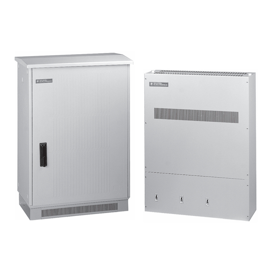
PRÉSENTATION Les appareils sont disponibles dans les versions : ....... Version Tableau montage dans une carcasse en acier au car- bone bichromé, avec un socle ayant quatre orifices pour fixa- tion au sol de l’armoire dans laquelle il sera installé. Version Intempérie, installation dans des armoires métalliques en acier au carbone et traitement de cataphorèse. -
Page 57: Contacts Sans Potentiel
• Contacts sans potentiel Les contacts électriques sont les éléments de commande qui brancheront ou débrancheront nos récepteurs (bobines, lumières, moteurs, etc.). Ces contacts sont placés dans les logements prévus à cet effet et actionnés par divers systè- mes, par exemple des boutons, interrupteurs, relais, etc. •... - Page 58 • Série RE2 Série de stabilisateurs statiques de tension pour des applications industrielles que SALICRU a développées et dont elle a obtenu le brevet mondial dans les années soixante-dix. • Triac Le triac est un dispositif semi-conducteur à trois terminaux, utilisé pour contrôler le flux de courant moyen vers une charge, avec la particularité...
- Page 59 - 59 -...
- Page 60 08460 Palautordera Tel. +34 93 848 24 00 sat@salicru.com...