Table des Matières
Publicité
Les langues disponibles
Les langues disponibles
Liens rapides
Publicité
Chapitres
Table des Matières

Sommaire des Matières pour Toshiba LONWORKS TCB-IFLN642TLE
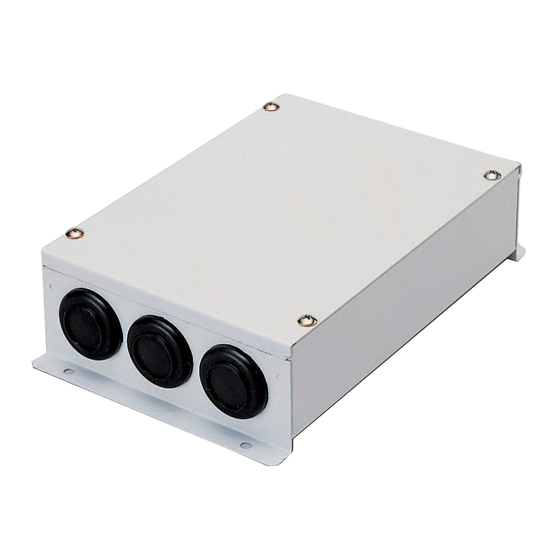
- Page 1 +00DE93419101-1_00Ta.book Page 1 Wednesday, February 9, 2011 5:27 PM LN INTERFACE Installation Manual Model name: TCB-IFLN642TLE English Installation Manual Français Manuel d’installation Deutsch Installationshandbuch Italiano Manuale d’installazione Toshiba...
-
Page 2: Table Des Matières
+00DE93419101-1_00Ta.book Page 1 Wednesday, February 9, 2011 5:27 PM Installation Manual LN INTERFACE • Thank you very much for purchasing this TOSHIBA LN interface. • Please read this manual carefully beforehand for proper installation of the LN interface. Contents 1 Precautions for Safety..........2 2 Introduction . -
Page 3: Precautions For Safety
Failure to do so may result in short-circuiting, overheating or fire. • Use predefined cable and connect them certainly. Keep the connecting terminal free from external force. It may cause an exothermic or a fire. – 2 – 2-EN Toshiba... -
Page 4: Introduction
TCC-LINK compatible air conditioners Applications/Functions/Features Applications The LN interface is used to control TCC-LINK compatible Toshiba air conditioners by the building control system using LON (Local Operating Network). Functions The LN interface converts signals between TCC-LINK signals for air conditioners and L ®... -
Page 5: Before Installation
Installation Space and Maintenance Space A side space for connecting through cable inlets and an upper space for maintenance must be reserved before installation. 100mm The other sides can be adjacent to surrounding objects. 100mm – 4 – 4-EN Toshiba... -
Page 6: Connection Of Power Cables/Communication Cables/Earth Wires
This appliance must be connected to the main power supply by a circuit breaker or switch with a contact separation of at least 3mm. • The TCC-LINK communication cable and the L ® communication cable have no polarity. ORKS • Fasten the screws to the terminal with torque of 0.5Nm. – 5 – 5-EN Toshiba... - Page 7 Indoor unit The LON terminator resistor is unit unit set on the upper L ® ORKS system side. Do not set it here. Remote Remote controller controller Power supply 220 - 240 VAC LN interface – 6 – 6-EN Toshiba...
-
Page 8: Setting
However, it will result in communication loss. Indoor unit central control address and SW1/SW2 setting Indoor unit Indoor unit Indoor unit Indoor unit central control central control central control central control address address address address – 7 – 7-EN Toshiba... - Page 9 ORKS A specific tool is used for the setting. Ask a professional engineer for this process. • SW8 Service pin for L ® system ORKS Used for Commissioning with the upper L ® system. ORKS – 8 – 8-EN Toshiba...
-
Page 10: Trial Operation
Re-set SW1 and SW2 to the number of connected indoor units, and set bit2 of SW3 to “OFF”. REQUIREMENT Be sure to re-set SW1 and SW2 correctly. Wrong setting may result in a malfunction when the unit is reset. – 9 – 9-EN Toshiba... - Page 11 ORKS indicator LED7 RESET Reset indicator Lights when reset operation is performed. LED8 SERVICE indicator ® ORKS (*) Ask the manufacturer of the upper system for trial operation check of the L system. ® ORKS – 10 – 10-EN Toshiba...
- Page 12 +00DE93419101-1_00Ta.book Page 11 Wednesday, February 9, 2011 5:27 PM Manuel d’installation INTERFACE LN • Un grand merci d’avoir acheter cette interface LN TOSHIBA. • Avant de procéder à l’installation, veuillez lire attentivement ce manuel pour être en mesure d’effectuer un montage convenable de la interface LN.
-
Page 13: Précautions De Sécurité
Dans le cas contraire, vous risquez de provoquer un court-circuit, une surchauffe, voire un incendie. • Utilisez un câble prédéfini et raccordez fermement. Evitez toute force externe sur la borne de raccordement. Cela pourrait entraîner un effet exothermique ou un incendie. – 12 – 2-FR Toshiba... -
Page 14: Introduction
Climatiseurs compatibles TCC-LINK Applications/Fonctions/Caractéristiques Applications L’interface LN permet de commander les climatiseurs Toshiba compatibles TCC-LINK par le système de contrôle des bâtiments à l’aide de LON (Local Operating Network). Fonctions L’interface LN convertit les signaux entre les signaux TCC-LINK des climatiseurs et les signaux L ®... -
Page 15: Avant L'installation
Espace requis pour l’installation et l’entretien Avant l’installation, vous devez allouer un espace latéral pour le branchement à travers les câbles d’entrée et un espace supérieur pour la maintenance. 100mm Les autres côtés peuvent être adjacents aux objets avoisinants. 100mm – 14 – 4-FR Toshiba... -
Page 16: Connexion Des Câbles D'alimentation/Câbles De Communication/Fils De Terre
3 mm. • Le câble de communication TCC-LINK et le câble de communication L ® n’ont pas de polarité. ORKS • Fixez les vis à la borne avec un couple de 0,5 Nm. – 15 – 5-FR Toshiba... - Page 17 U2 U1 Unité Unité Unité intérieure intérieure intérieure La résistance de terminaison LON est placée côté système L ® ORKS Télécommande Télécommande supérieur. Ne la placez pas ici. Alimentation électrique 220 - 240 VCA Interface LN – 16 – 6-FR Toshiba...
-
Page 18: Réglage
Adresse de la commande centralisée de l’unité intérieure et réglage SW1/SW2 Adresse de la Adresse de la Adresse de la Adresse de la commande commande commande commande centralisée de centralisée de centralisée de centralisée de l’unité intérieure l’unité intérieure l’unité intérieure l’unité intérieure – 17 – 7-FR Toshiba... - Page 19 Ce réglage nécessite un outil spécifique. Contactez un ingénieur pour en savoir plus sur cette procédure. • SW8 Code PIN de service pour le système L ® ORKS Utilisé pour la mise en service avec le système L ® supérieur. ORKS – 18 – 8-FR Toshiba...
-
Page 20: Essai De Fonctionnement
Modifiez le réglage de SW1 et SW2 selon le nombre d’unités intérieures connectées, et réglez le bit 2 de SW3 sur « OFF ». EXIGENCE Veillez à modifier le réglage de SW1 et SW2 correctement. Un réglage incorrect peut entraîner un dysfonctionnement une fois l’unité réinitialisée. – 19 – 9-FR Toshiba... - Page 21 ORKS ® ORKS LED7 RESET Indicateur de réinitialisation S’allume lors de la réinitialisation. LED8 SERVICE Indicateur L ® ORKS (*) Contactez le fabricant du système supérieur concernant l’essai de fonctionnement du système L ® ORKS – 20 – 10-FR Toshiba...
- Page 22 +00DE93419101-1_00Ta.book Page 21 Wednesday, February 9, 2011 5:27 PM Installationshandbuch LN-SCHNITTSTELLE • Vielen Dank, dass Sie sich für diese LN-Schnittstelle von TOSHIBA entschieden haben. • Bitte lesen Sie dieses Handbuch sorgfältig vorher durch, um die Installation der LN-Schnittstelle richtig auszuführen.
-
Page 23: Vorsichtsmaßnahmen Für Die Sicherheit
Wenn das nicht geschieht, besteht die Gefahr von Kurzschluss, Überhitzung oder Bränden. • Verwenden Sie nur die vorgeschriebenen Kabel und schließen Sie diese sicher an. Achten Sie darauf, dass auf die Anschlusskontakte keine äußeren Kräfte einwirken. Dies könnte eine exotherme Reaktion oder Feuer auslösen. – 22 – 2-DE Toshiba... -
Page 24: Einleitung
Geeignete Klimageräte Mit dem TCC-LINK kompatible Klimageräte Anwendungen/Funktionen/Besonderheiten Anwendungen Die LN-Schnittstelle wird von der Gebäudesteuerung verwendet, um mit dem TCC-LINK kompatible Toshiba- Klimageräte über ein LON (lokales Netzwerk) zu steuern. Funktionen Die LN-Schnittstelle wandelt Signale zwischen TCC-LINK-Signalen für Klimageräte und L ®... -
Page 25: Vor Der Installation
Achten Sie bei der Montage darauf, dass an einer Seite genügend Platz für den Anschluss durch Kabelanschlussöffnungen und oben ein ausreichender Zugang für die 100mm Wartung vorhanden ist. Bei den übrigen Seiten ist kein Abstand zu nebenstehenden Geräten erforderlich. 100mm – 24 – 4-DE Toshiba... -
Page 26: Anschluss Der Stromkabel/Kommunikationskabel/Erdungskabel
Das Gerät muss über einen Schutzschalter oder eine Sicherung mit einem Mindestkontaktabstand von 3 mm an die Netzversorgung angeschlossen werden. • Das TCC-LINK -Kommunikationskabel und das L ® -Kommunikationskabel haben keine Polarität. ORKS • Ziehen Sie die Schrauben an der Klemme mit einem Drehmoment von 0,5 Nm an. – 25 – 5-DE Toshiba... - Page 27 Kabel nicht am Klemmenblock an U2 U1 U2 U1 U2 U1 Raumgerät Raumgerät Raumgerät Der LON-Abschlusswiderstand wird am übergeordneten L -System ® ORKS gesetzt. Setzen Sie ihn nicht hier. Fernbe-dienung Fernbe-dienung Stromversorgung 220 - 240 VAC LN-Schnittstelle – 26 – 6-DE Toshiba...
-
Page 28: Einstellung
Zentralsteuerungsadresse wie in der Tabelle unten angegeben ein. Hinweis: Das System arbeitet normal, wenn der Einstellwert größer als das Maximum ist. Es kommt jedoch zu Kommunikationsstörungen. Innengerät-Zentralsteuerungsadresse und SW1/SW2 einstellen Innengerät- Innengerät- Innengerät- Innengerät- Zentralsteuerun Zentralsteuerun Zentralsteuerun Zentralsteuerun gsadresse gsadresse gsadresse gsadresse – 27 – 7-DE Toshiba... - Page 29 Für diese Einstellung wird ein besonderes Tool benötigt. Fragen Sie einen Fachingenieur nach der Vorgehensweise. • SW8 Servicekontakt für L ® -System ORKS Wird für den Vorgang „Commissioning“ beim übergeordneten L ® -System verwendet. ORKS – 28 – 8-DE Toshiba...
-
Page 30: Probebetrieb
Setzen Sie SW1 und SW2 auf die Anzahl der angeschlossenen Innengeräte zurück und setzen Sie Bit 2 von SW3 auf „OFF“. ANFORDERUNG Achten Sie darauf, SW1 und SW2 auf die korrekten Werte zurückzusetzen. Eine falsche Einstellung kann beim Rücksetzen des Geräts zu einer Funktionsstörung führen. – 29 – 9-DE Toshiba... - Page 31 Blinkt bei L -Kommunikation. ® ORKS Kommunikationsstatusanzeige LED7 RESET Reset-Anzeige Leuchtet, wenn der Reset-Vorgang ausgeführt wird. LED8 SERVICE ® -Anzeige ORKS (*) Bitten Sie den Hersteller des übergeordneten Systems um eine Probebetrieb-Prüfung des L -Systems. ® ORKS – 30 – 10-DE Toshiba...
- Page 32 +00DE93419101-1_00Ta.book Page 31 Wednesday, February 9, 2011 5:27 PM Manuale d’installazione INTERFACCIA LN • Grazie per aver acquistato questa interfaccia TOSHIBA LN. • Prima di procedere con l’installazione le raccomandiamo di leggere a fondo il presente manuale. Indice 1 Precauzioni per la sicurezza..........32 2 Introduzione .
-
Page 33: Precauzioni Per La Sicurezza
In caso contrario si potrebbero generare cortocircuiti, surriscaldamenti o persino incendi. • Utilizzare il cavo predefinito e collegarlo in modo corretto. Conservare il contatto di collegamento lontano da forze esterne. Può provocare un’esotermia o un incendio. – 32 – 2-IT Toshiba... -
Page 34: Introduzione
Condizionatori compatibili TCC-LINK Applicazioni/Funzioni/Caratteristiche Applicazioni L’interfaccia LN consente di controllare i condizionatori Toshiba compatibili TCC-LINK mediante la creazione di un sistema di controllo dell’edificio utilizzando la LON (Local Operating Network, rete operativa locale). Funzioni L’interfaccia LN converte i segnali tra i segnali TCC-LINK per i condizionatori e i segnali L ®... -
Page 35: Prima Di Procedere Con L'installazione
Spazio d’installazione e per manutenzione Prima dell’installazione, lasciare uno spazio laterale per il collegamento degli ingressi dei cavi e uno spazio superiore per la manutenzione. 100mm Gli altri lati possono essere adiacenti agli oggetti circostanti. 100mm – 34 – 4-IT Toshiba... -
Page 36: Collegamento Di Cavi Di Alimentazione/Cavi Di Comunicazione/Cavi Di Terra
3 mm di separazione fra i contatti. • Il cavo di comunicazione The TCC-LINK e il cavo di comunicazione L ® sono senza polarità. ORKS • Serrare le viti al contatto con una coppia di 0,5 Nm. – 35 – 5-IT Toshiba... - Page 37 Unità interna La resistenza di terminazione LON interna interna è impostata sul lato superiore del sistema L ® . Non deve ORKS Telecomando Telecomando essere installata qui. Alimentazione elettrica 220 - 240 VCA Interfaccia LN – 36 – 6-IT Toshiba...
-
Page 38: Impostazione
Tuttavia, questo provoca una perdita di comunicazione. Impostazione dell’indirizzo di controllo centrale dell’unità interna e SW1/SW2 Indirizzo di Indirizzo di Indirizzo di Indirizzo di controllo controllo controllo controllo centrale centrale centrale centrale dell’unità dell’unità dell’unità dell’unità interna interna interna interna – 37 – 7-IT Toshiba... - Page 39 Per l’impostazione viene utilizzato uno strumento specifico. Per informazioni su questo processo, rivolgersi a un tecnico professionista. • SW8 Perno di servizio per il sistema L ® ORKS Utilizzato per la messa in funzione con il sistema superiore L ® ORKS – 38 – 8-IT Toshiba...
-
Page 40: Prova Di Funzionamento
Reimpostare SW1 e SW2 sul numero di unità interne collegate e impostare bit2 di SW3 su “OFF”. REQUISITO Assicurarsi di reimpostare correttamente SW1 e SW2. Delle impostazioni errate potrebbero provocare un problema di funzionamento al momento del ripristino dell’unità. – 39 – 9-IT Toshiba... - Page 41 Indicatore di reset Appare quando viene eseguita l’operazione di ripristino. LED8 SERVICE Indicatore L ® ORKS (*) Chiedere al produttore del sistema superiore di effettuare il controllo dell’operazione di prova del sistema L ® ORKS – 40 – 10-IT Toshiba...
- Page 42 Manuale d’installazione INTERFACCIA LN MEMO ......................................................................................................................................................................................................................................................................................................................................................................................................................................................................................................................................................................................................................................– 41 – Toshiba...
- Page 43 Manuale d’installazione INTERFACCIA LN MEMO ......................................................................................................................................................................................................................................................................................................................................................................................................................................................................................................................................................................................................................................– 42 – Toshiba...
- Page 44 +00DE93419101-1_00Ta.book Page 43 Wednesday, February 9, 2011 5:27 PM DE93419101-1 Toshiba...