Publicité
Les langues disponibles
Les langues disponibles
Liens rapides
Publicité

Manuels Connexes pour habitat et jardin Family

Sommaire des Matières pour habitat et jardin Family
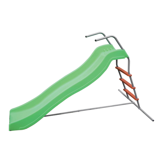
- Page 1 Family 1293_68445...
- Page 2 SAFETY NOTES To prevent damage and accidents to persons and/or property, the following instructions and advice must be followed: 1. Thoroughly read all parts of this manual and strictly follow the instructions before using. 2. Do not use any accessories other than those provided and /or specified by the manufacturer.
- Page 3 COMPONENT LIST Description Illustration M6 30mm bolt M6 35mm bolt M6 25mm bolt M6 washer Spring wahser Domenut Tie bar Ladder step Ladder stabilizer bar Wavy slider chute...
- Page 4 COMPONENT LIST Description Illustration Tie bar Handrail tube Plastic spacer Ground anchor 40 mm bolt / 15mm bolt M6 Square washer Plastic cap Chute bottom support tube required: 1. Philips head screw driver 2. Combination wrench 10...
- Page 5 Assembly Steps: Step 1 Assembling The Ladder 1.-1 Fix step H to handrail tube L using bolt set (bolt S x 1 + square washer U x 1 ). 1.-2 Attach the handrail tube L to ladder stabilizer bar I using bolt set (bolt B x 1 + washer D x 1 + spring washer E x 1 + domenut F x 1).
- Page 6 2.-2 By using bolt set ( bolt B x 1 + washer D x 1 + spring washer E x 1 + domenut F x 1) to make slide chute and handrail L tie together. Step 3 Assembling the Tie Bar 3.-1 Attach the tie bar K and G using bolt set (bolt C x 1 + washer D x 1 + spring washer E x 1 + domenut F x 1).
- Page 7 Step 5 Assembling the Gound Anchors 5.-1 Fix each side of ladder stabilizer bar on ground using ground anchor O. 5.-2 Insert plastic cap R into each end of handrail L and end of ladder stabilizer bar I. 5.-3 When selecting a place to install the equipment, take into account the space required for the training activity.
- Page 8 Care and Maintenance 1. This equipment must be assembled and checked by an adult. 2. Regularly check all nuts and bolts for tightness before use and replace any worn, defective or missing parts. DO NOT try to repaire broken parts. 3.
- Page 9 Explosive Drawing...
- Page 10 REGLES DE SECURITE Afin de prévenir d’éventuels accidents ou dégâts corporels ou matériels les instructions qui suivent doivent être scrupuleusement respectées : 1. Lire minutieusement l’intégralité de ce guide de montage et respecter toutes les instructions de montage avant usage. 2.
- Page 11 21. Un assemblage inadéquat de cet équipement peut causer des risques de blessures graves aux utilisateurs 22. Conserver ce manuel dans un endroit sûr en cas de consultations ultérieures aux montages 23. Age min/max : 3-10 ans. 24. Ne pas placer ses mains prêtes d’éléments amovibles. Page 3 of 8...
- Page 12 LISTE DES PIECES Description Illustration Boulon M6 30mm Boulon M6 35mm Boulon M6 25mm Rondelles Rondelles élastiques Ecrous à calotte Armature Marches Barre stabilisatrice Glissière...
- Page 13 LISTE DES PIECES Description Illustration Armature Montant Clé Fixation au sol Boulons 40 mm / Boulons 15 mm Rondelle carrée M6 E m bouts plastiques Barre de support bas de glissière required: 1. Tournevis cruciforme 2. Clé mixte de 10...
- Page 14 Etapes d’assemblage Etape 2 Etape 1 Etape 4 Etape 3 Etape 1 Montage de l’échelle 1.-1 Fixer les marches (H) au montant de l’échelle (L) en utilisant 1 Boulon (S) + 1 Rondelle carrée (U) 1.-2 Fixer le montant (L) à la barre stabilisatrice (I) en utilisant 1 Boulon (B) + 1 Rondelle élastique (E) + 1 Ecrou à...
- Page 15 2.-2 Utiliser 1 Boulon (B) + 1 Rondelle (D) + 1 Rondelle élastique (E) + 1 Ecrou à calotte (F) pour la fixation du montant à la glissière Etape 3 Assemblage de la barre de stabilisation 3.-1 Fixer les armatures (K) et (G) en utilisant 1 Boulon (C) + 1 Rondelle (D) + 1 Rondelle élastique (E) + 1 Ecrou à...
- Page 16 Etape 5 Fixation au Sol 5.-1 Ancrer chaque partie de la barre stabilisatrice au sol en utilisant les fixations au sol (O) fournies. 5.-2 Ajouter un embout en plastique (R) à chaque extrémité du montant de l’échelle (L) ainsi qu’aux extrémités de la barre stabilisatrice (I). 5.-3 Choisir le lieu d’installation de votre toboggan en veillant à...
- Page 17 5.-5 Ne pas installer votre toboggan dans un endroit fermé et humide qui pourrait causer une rouille prématurée Page 7 of 8...
- Page 18 Conseils d’entretien 1. Cet équipement doit être assemblé par un adulte. 2. Vérifier le serrage de tous les écrous et boulons avant chaque utilisation et procéder au remplacement des éléments usés, défectueux ou manquants. Ne pas essayer de réparer les éléments endommagés. 3.
- Page 19 Vue éclatée...
- Page 20 REGLAS DE SEGURIDADES Las instrucciones siguientes deben ser imperativamente respetadas para evitar accidentes y daños corporales y materiales: 1. Leer minuciosamente todo el guía de montaje y respetar todas las instrucciones de seguridades y de montaje antes el uso. 2. No utilice otros accesorios que los que son específicamente provistos o recomendados por el fabricante para el montaje de su producto.
- Page 21 21. Un montaje no adecuado de este producto puede provocar lesiones graves a los utilizadores. 22. Conserve este manual en un lugar seguro si quiere consultarle después del montaje. 23. Año min/máx.: 3-10 años. poner manos sobre elementos muevan.
- Page 22 LISTA DE PIEZAS Description Illustration M6 30mm bolt M6 35mm bolt M6 25mm bolt M6 washer Spring wahser Domenut Tie bar Ladder step Ladder stabilizer bar Wavy slider chute...
- Page 23 LISTA DE PIEZAS Description Illustration Tie bar Handrail tube Plastic spacer Ground anchor 40 mm bolt / 15mm bolt M6 Square washer Plastic cap Chute bottom support tube required: 1. Philips head screw driver 2. Combination wrench 10...
- Page 24 Etapas de montaje Etapa 2 Etapa 1 Etapa 4 Etapa 3 Etapa 1 Montaje de la escalera 1.-1 Fijar los peldaños (H) sobre el cuerpo de la escalera (L) utilizando 1 Perno (S) + 1 Tuerca cuadrada (U) 1.-2 Fijar el tubo de la escalera (L) con la barra estabilizadora (I) utilizando 1 Perno (B) + 1 Tuerca elástica (E) + 1 Tuerca ciega (F) Etapa 2 Montaje de la corredera à...
- Page 25 2.-2 Utilizar 1 Perno (B) + 1 Arandela (D) + 1 Tuerca elástica (E) + 1 Tuerca ciega (F) para la fijación de los tubos sobre la corredera Etapa 3 Montaje de la barra de estabilización 3.-1 Fijar las armaduras (K) y (G) utilizando 1 Perno (C) + 1 Arandela (D) + 1 Tuerca elástica (E) + 1 Tuerca ciega (F) 3.-2 Fijar la armadura (G) sobre la barra de estabilización utilizando 1 Perno (B) + 1 Arandela (D) + 1 Tuerca elástica (E) + 1 Tuerca ciega (F)
- Page 26 Etapa 5 Fijación en el suelo 5.-1 Fijar cada parte de la barra de estabilización en el suelo utilizando las fijaciones al suelo (O) proveídos. 5.-2 Añadir una punta de plástico (R) en cada extremidad del cuerpo de la escalera (L) así como las extremidades de la barra de estabilización (I). 5.-3 Elija el lugar de instalación de su tobogán tomando una área de seguridad, deje un espacio de al menos 1,5 metro alrededor de su tobogán.
- Page 27 Consejos de mantenimiento 1. Este producto debe ser montado por un adulto. 2. Verifique les pernos y los tornillos son bien apretados antes cada uso y reemplace cualquier elemento que es desgastada, que no funciona o que falta. No pruebe reparar les elementos desgastados.
- Page 28 Vista en despiece ordenado...
- Page 29 NOTE DI SICUREZZA Per evitare gli incidenti e di danneggiare il prodotto, bisogna tenere conto delle istruzioni e dei consigli seguenti: 1. Leggere con attenzione tutto il manuale e seguire le istruzioni prima di usare il prodotto. 2. Non utilizzare accessori che non sono stati forniti e/o specificati dal fabbricante. 3.
- Page 30 LISTA DEI COMPONENTI Description Illustration M6 30mm bolt M6 35mm bolt M6 25mm bolt M6 washer Spring wahser Domenut Tie bar Ladder step Ladder stabilizer bar Wavy slider chute...
- Page 31 LISTA DEI COMPONENTI Description Illustration Tie bar Handrail tube Plastic spacer Ground anchor 40 mm bolt / 15mm bolt M6 Square washer Plastic cap Chute bottom support tube required: 1. Philips head screw driver 2. Combination wrench 10...
- Page 32 Passi d’assemblaggio Passo 1 Montaggio della scala 1.-1 Fissare gli scalini (H) con le barre della scala (L) usando 1 bullone (S) + 1 rondella quadrata (U) 1.-2 Fissare le barre della scala (L) alla barra di stabilizzazione (I) usando 1 bullone (B) + 1 rondella elastica (E) + 1 dado a calotta (F)
- Page 33 Passo 2 Assemblaggio dello scivolo e della scala 2.-1 Assemblare lo scivolo (J) alla scala (L), la scala deve essere fissata via i buchi che si trovano in cima dello scivolo 2.-2 Utilizzare 1 bullone (B) + 1 Rondella (D) + 1 rondella elastica (E) + 1 dado a calotta (F) per fissare la scala allo scivolo.
- Page 34 Passo 4 Assemblaggio della barra di supporto 4.-1 Fissare la barra di supporto (P) alla struturra (K) utilizzando 1 bullone (A) + 1 rondella (D) + 1 rondella elastica (E) + 1 dado a callota (F) 4.-2 Fissare la parte sotto dello scivolo alla barra di supporto via i buchi che si trovano in cima alla barra di supporto utilizzando 1 bullone (T).
- Page 35 5.-3 Scegliere il posto dove sarà installato lo scivolo facendo attenzione che ci sia uno spazio minimo di sicurezza di 1,5 metri intorno allo scivolo. Non piazzare lo scivolo vicino ad elementi sporgenti come dei recinti (reti) o rami che possono essere pericolosi.
- Page 36 Consigli di manutenzione 1. Questo prodotto deve essere montato e verificato da un adulto. 2. Verificare frequentemente che le viti e i bulloni siano stretti prima di utilizzare il prodotto e bisogna rimpiazzare le parti danneggiate, usate e che mancano. Non provare di riparare le parti rotte. 3.
- Page 37 Vista esplosa...