Télécharger Imprimer la page
Danfoss 088U0230 Manuel D'utilisation
Masquer les pouces Voir aussi pour 088U0230:

Publicité

Les langues disponibles
  • FR

Les langues disponibles

  • FRANÇAIS, page 22

Liens rapides

088U0230
Instruction CF-RU Repeater Unit
GB
Instruktion CF-RU Signalverstärker
D
Vejledning CF-RU Repeaterenhed
DK
Instruction Réémetteur CF-RU
F
Bruksanvisning CF-RU Repeater-enhet
SE
Instrukcja obsługi wzmacniacza sygnału CF-RU
PL
Handleiding Signaalversterker CF-RU
NL
Istruzioni Ripetitore CF-RU
I
CF-RU-toistimen käyttöohje
FI
Návod k použití zesilovače CF-RU
CZ

Publicité

loading

Sommaire des Matières pour Danfoss 088U0230

  • Page 1 088U0230 Instruction CF-RU Repeater Unit Instruktion CF-RU Signalverstärker Vejledning CF-RU Repeaterenhed Instruction Réémetteur CF-RU Bruksanvisning CF-RU Repeater-enhet Instrukcja obsługi wzmacniacza sygnału CF-RU Handleiding Signaalversterker CF-RU Istruzioni Ripetitore CF-RU CF-RU-toistimen käyttöohje Návod k použití zesilovače CF-RU...
  • Page 2 Instrukce........57 VI.UH.N6.1T Produced by Danfoss Floor Heating Hydronics 08.2010...
  • Page 3: Table Des Matières

    8. Figures and illustrations....... . A1-A2 VI.UH.N6.1T Produced by Danfoss Floor Heating Hydronics 08.2010...
  • Page 4: Functional Overview

    Back plate lock/unlock (turn 90°). Screw hole for wall mounting. Screw and wall plug. Mounting with screws Back plate. Screw hole for wall mounting. Screw and wall plug. Front Cover – fig. 3 Front cover release. Push Button – fig. 4 Push button (for installation/transmission test). VI.UH.N6.1T Produced by Danfoss Floor Heating Hydronics 08.2010...
  • Page 5: Installation

    • Not satisfactory - LED flashes 5 times. Installation in the Danfoss Link™ system 1. Install the Repeater Unit on the Danfoss Link™ CC by adding it as a service device (see the Danfoss Link™ CC manual). 2. Activate Install mode on Repeater Unit: • Release the front cover, see fig. 3.
  • Page 6: Placing And Mounting

    • LED flashes 5 times. No transmission to room / Repeater Unit • Try to relocate the Repeater Unit. • Or install one or up to three Repeater Units and place them between the Controller and Room Thermostat. VI.UH.N6.1T Produced by Danfoss Floor Heating Hydronics 08.2010...
  • Page 7: Uninstallation

    Number of Repeater Units in a chain (up to) Transmission power <1mW Supply voltage 230 V AC / 4.5V Ambient temperature 0-50°C IP class 7. Troubleshooting Error indication Possible Causes The LED flashes 5 times Installation/Link Test is unsatisfactory VI.UH.N6.1T Produced by Danfoss Floor Heating Hydronics 08.2010...
  • Page 8 VI.UH.N6.1T Produced by Danfoss Floor Heating Hydronics 08.2010...
  • Page 9 Instruktion CF-RU Signalverstärker Inhaltsverzeichnis 1. Funktionsübersicht ..............10 2. Installation / Anmeldung ............. 11 3. Platzierung und Montage ............12 4. Funk - Verbindungstest ..............12 5. Reset / Zurücksetzen ..............13 6. Technische Daten ................13 7. Fehlersuche ................... 14 8. Abbildungen und Illustrationen ..........A1-A2 VI.UH.N6.1T Hergestellt von Danfoss Floor Heating Hydronics 08.2010...
  • Page 10: Funktionsübersicht

    Schraubenloch für Wandmontage. Schraube und Dübel. Montage mit Schrauben - Fig. 2 Hintere Abdeckung. Schraubenloch für Wandmontage. Schraube und Dübel. Vordere Abdeckung – Fig. 3 Lösevorrichtung der vorderen Abdeckung (z.B. durch 2 mm Inbusschlüssel) Öffnung gemäß Fig.3 durchstoßen. Druckknopf – Fig. 4 Druckknopf (für Installation/Funk-Verbindungstest). VI.UH.N6.1T Hergestellt von Danfoss Floor Heating Hydronics 08.2010...
  • Page 11: Installation / Anmeldung

    • Nicht zufriedenstellend – LED blinkt fünfmal. Installation im Danfoss Link™-System 1. Installieren Sie den Signalverstärker auf dem Danfoss Link™ CC durch Hinzufügen als Servicegerät (siehe Danfoss Link™ CC-Handbuch). 2. Aktivierung des Installationsmodus auf dem Signalverstärker: • Entriegeln Sie die Frontabdeckung, siehe Abb. 3.
  • Page 12: Platzierung Und Montage

    • Betätigen Sie den Druckknopf • Die LED wechselt zu „EIN“. Der Verbindungstest ist ok • Die LED wechselt zu „AUS“. • Befestigen Sie die vordere Abdeckung erneut. Der Verbindungstest ist nicht ok • Die LED blinkt 5 Mal. VI.UH.N6.1T Hergestellt von Danfoss Floor Heating Hydronics 08.2010...
  • Page 13: Reset / Zurücksetzen

    6. Technische Daten Kabellänge (Stromversorgung) Sendefrequenz 868,42 MHz Sendebereich in Gebäuden (bis zu) 30 m Anzahl der Signalverstärker in Reihe (bis zu) Sendeleistung <1mW Versorgungsspannung 230 V AC / 4,5V Umgebungstemperatur 0-50 °C IP-Klasse VI.UH.N6.1T Hergestellt von Danfoss Floor Heating Hydronics 08.2010...
  • Page 14: Fehlersuche

    Instruktion CF-RU Signalverstärker 7. Fehlersuche Fehleranzeige Mögliche Ursache Die LED blinkt 5 Mal Bitte Funk - Verbindungstest entsprechend Kapitel 4 wieder- (Fig. 4) holen, evtl. weitere Signalverstärker zwischen Hauptregler und Raumthermostat platzieren. VI.UH.N6.1T Hergestellt von Danfoss Floor Heating Hydronics 08.2010...
  • Page 15 Vejledning CF-RU Repeaterenhed Indhold 1. Funktionsoversigt ................ 16 2. Installation ..................17 3. Placering og montering ............... 18 4. Transmissionstest ................ 18 5. Afinstallation ................19 6. Specifikationer ................19 7. Fejlfinding ..................19 8. Figurer og illustrationer ............A1-A2 VI.UH.N6.1T Fremstillet af Danfoss Floor Heating Hydronics 08.2010...
  • Page 16: Funktionsoversigt

    • Hurtig blinken Flimrer Bagside - fig. 2 Bagplade. Løsning af frontdæksel. Bagpladelås (drej 90°). Skruehul til vægmontering. Skrue og rawlplug. Montering med skruer Bagplade. Skruehul til vægmontering. Skrue og rawlplug. Frontdæksel - fig. 3 Løsning af frontdæksel. Trykknap – fig. 4 Trykknap (til installations/transmissionstest). VI.UH.N6.1T Fremstillet af Danfoss Floor Heating Hydronics 08.2010...
  • Page 17: Installation

    • Ikke tilfredsstillende - Lysdiode blinker fem gange. Installation i Danfoss Link™-systemet 1. Installer Repeaterenheden på Danfoss Link™ CC ved at tilføje den som en serviceenhed (se manualen til Danfoss Link™ CC). 2. Aktivér Installationstilstand på Repeaterenhed: • Løsn frontdækslet, se fig. 3.
  • Page 18: Placering Og Montering

    • Sæt frontdækslet på plads igen. Linktesten er utilfredsstillende • Lysdioden blinker 5 gange. Ingen transmission til rummet/Repeaterenheden • Prøv at genplacere Repeaterenheden. • Eller installer op til tre Repeaterenheder, og anbring dem mellem masterregulatoren og rumtermostaten. VI.UH.N6.1T Fremstillet af Danfoss Floor Heating Hydronics 08.2010...
  • Page 19: Afinstallation

    Transmissionsrækkevidde i bygninger (op til) Antal repeaterenheder i en kæde (op til) Transmissionseffekt <1mW Forsyningspænding 230 V AC / 4,5V Omgivelsestemperatur 0-50°C IP-klasse 7. Fejlfinding Fejlindikation Mulig årsag Lysdioden blinker fem gange Installlations/linktesten er ikke tilfredsstillende VI.UH.N6.1T Fremstillet af Danfoss Floor Heating Hydronics 08.2010...
  • Page 20 VI.UH.N6.1T Produced by Danfoss Floor Heating Hydronics 08.2010...
  • Page 21 Instruction Réémetteur CF-RU Index 1. Présentation des fonctions ............22 2. Installation ..................23 3. Mise en place et montage ............24 4. Test de transmission ..............24 5. Désinstallation ................25 6. Spécifications ................25 7. Dépannage ..................25 8. Tableaux et illustrations ............A1-A2 VI.UH.N6.1T Produit par Danfoss Floor Heating Hydronics 08.2010...
  • Page 22: Présentation Des Fonctions

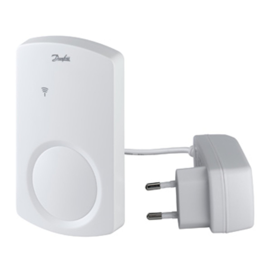
    Verrouiller/déverrouiller plaque arrière (tourner 90°). Orifice vis pour montage mural. Vis et chevilles murales. Montage avec vis Plaque arrière. Orifice vis pour montage mural. Vis et chevilles murales. Couvercle avant – fig. 3 Libérer couvercle avant. Bouton poussoir – fig. 4 Bouton poussoir (pour test installation/transmission). VI.UH.N6.1T Produit par Danfoss Floor Heating Hydronics 08.2010...
  • Page 23: Installation

    • Non satisfaisant : le voyant clignote 5 fois. Installation dans le système Danfoss Link™ 1. Installez le répétiteur sur le régulateur central Danfoss Link™ CC en l’ajou- tant en tant qu’appareilde service (voir le manuel du Danfoss Link™ CC). 2. Activez le mode d’installation sur le répétiteur : •...
  • Page 24: Mise En Place Et Montage

    • La diode LED clignote 5 fois. Pas de transmission vers la pièce / le répétiteur • Essayer de changer l’emplacement du répétiteur. • Ou installer un ou jusqu’à trois répétiteurs et les placer entre. le régulateur principal et les thermostats d’ambiance. VI.UH.N6.1T Produit par Danfoss Floor Heating Hydronics 08.2010...
  • Page 25: Désinstallation

    Puissance transmission <1mW 230 V courant Tension alimentation alternatif / 4,5V Température ambiante 0-50°C Indice de protection IP 7. Dépannage Indication erreur Cause possible Le test raccordement/installation n’est pas La diode LED clignote 5 fois satisfaisant VI.UH.N6.1T Produit par Danfoss Floor Heating Hydronics 08.2010...
  • Page 26 VI.UH.N6.1T Produced by Danfoss Floor Heating Hydronics 08.2010...
  • Page 27 Bruksanvisning CF-RU Repeater-enhet Innehåll 1. Funktionsöversikt ................. 28 2. Installation ..................29 3. Placering och montering .............. 30 4. Kommunikationstest ..............30 5. Avinstallation ................31 6. Specifikationer ................31 7. Felsökning ..................31 8. Figurer och illustrationer ............A1-A2 VI.UH.N6.1T Tillverkad av Danfoss Floor Heating Hydronics 08.2010...
  • Page 28: Funktionsöversikt

    Lås till locket på baksidan (vrid 90°). Skruvhål för väggmontering. Skruv och plugg. Montering med skruvar Lock på baksidan. Skruvhål för väggmontering. Skruv och plugg. Lock på framsidan - bild 3 Demontering av locket på framsidan. Tryckknapp - bild 4 Tryckknapp (för installations-/transmissionstest). VI.UH.N6.1T Tillverkad av Danfoss Floor Heating Hydronics 08.2010...
  • Page 29: Installation

    • Inte tillfredsställande - Dioden blinkar 5 gånger. Installation i Danfoss Link™-system 1. Installera Repeater-enheten på Danfoss Link™ CC genom att lägga till den som en service enhet (se handboken för Danfoss Link™ CC). 2. Aktivera Installationsläge på Repeater-enheten: • Frigör frontstycket, se bild 3.
  • Page 30: Placering Och Montering

    • Sätt tillbaka locket på framsidan. Förbindelsetestet är otillfredsställande • Indikatorn blinkar 5 gånger. Ingen kommunikation till rummet/repeater-enheten • Prova att sätta tillbaka Repeater-enheten. • Eller installera upp till tre Repeater-enheter och placera dem mellan master- regulatorn och rumstermostaten. VI.UH.N6.1T Tillverkad av Danfoss Floor Heating Hydronics 08.2010...
  • Page 31: Avinstallation

    Antal repeater-enheter i en kedja (upp till) Kommunikationseffekt <1 mW Försörjningsspänning 230 V AC / 4,5V Omgivningstemperatur 0-50 °C IP-klass 7. Felsökning Felindikation Möjlig orsak Indikatorerna blinkar fem gånger Installations-/förbindelsetestet är inte tillfreds ställande VI.UH.N6.1T Tillverkad av Danfoss Floor Heating Hydronics 08.2010...
  • Page 32 VI.UH.N6.1T Produced by Danfoss Floor Heating Hydronics 08.2010...
  • Page 33: Spis Treści

    Instrukcja obsługi wzmacniacza sygnału CF-RU Spis treści 1. Przegląd funkcji ................34 2. Instalacja ..................35 3. Ustawienie na wybranym miejscu i mocowanie ......36 4. Test transmisji ................36 5. Odinstalowanie ................37 6. Specyfikacje .................. 37 7. Usuwanie usterek ................. 37 8. Rysunki ..................A1-A2 VI.UH.N6.1T Wyprodukowane przez Danfoss Floor Heating Hydronics 08.2010...
  • Page 34: Przegląd Funkcji

    Blokada/zwolnienie blokady tylnej pokrywy (przekręcić o 90°). Otwór do montażu ściennego. Śróba montażowa. Montaż za pomocą śrub Tylna płyta. Otwór do montażu ściennego. Śruba montażowa. Przednia pokrywa – rys. 3 Zwolnienie przedniej pokrywy. Przycisk – rys. 4 Przycisk (dla celów montażu / testu transmisji). VI.UH.N6.1T Wyprodukowane przez Danfoss Floor Heating Hydronics 08.2010...
  • Page 35: Instalacja

    • Niepoprawny – dioda błyska 5 razy. Montaż w systemie Danfoss Link™ 1. Zainstalować wzmacniak na Danfoss Link™ CC, dodając go jako urządzenie usługowe (patrz instrukcja obsługi Danfoss Link™ CC). 2. Aktywacja trybu instalacji na wzmacniaku: • Zwolnić blokadę przedniej pokrywy – rys. 3.
  • Page 36: Ustawienie Na Wybranym Miejscu I Mocowanie

    • Ponownie zamocować pokrywę. Niepoprawny test połączenia • Dioda miga 5 razy. Brak transmisji do pomieszczenia / wzmacniacza sygnału • Umieścić wzmacniacz w inny miejscu. • Lub zamontować od 1 do 3 wzmacniaczy i umieścić je między regulatorem a termostatem pomieszczenia. VI.UH.N6.1T Wyprodukowane przez Danfoss Floor Heating Hydronics 08.2010...
  • Page 37: Odinstalowanie

    Liczba wzmacniaczy w sieci (maks.) Moc transmisji <1 mW Napięcie zasilania 230 V prąd zmienny/4,5V Temperatura otoczenia 0-50 °C Klasa IP 7. Usuwanie usterek Wskazanie błędu Możliwe przyczyny Dioda miga 5 razy Test montażu / połączenia niepoprawny VI.UH.N6.1T Wyprodukowane przez Danfoss Floor Heating Hydronics 08.2010...
  • Page 38 VI.UH.N6.1T Produced by Danfoss Floor Heating Hydronics 08.2010...
  • Page 39 Handleiding Signaalversterker CF-RU Inhoud 1. Functies overzicht ................. 40 2. Installatie (aanmelden) ..............41 3. Plaatsing en montage ..............42 4. Verbindingstest ................43 5. Afmelden / Resetten ..............43 6. Specificaties .................. 44 7. Probleemoplossing ..............44 8. Afbeeldingen ................A1-A2 VI.UH.N6.1T Geproduceerd door Danfoss Floor Heating Hydronics 08.2010...
  • Page 40: Functies Overzicht

    • Geen licht • Knippert langzaam Knippert langzaam • Knippert snel Knippert snel Achterzijde – fig. 2 Muurplaat. Dekselopener. Muurplaat vergrendelen/ontgrendelen (90° draaien). Schroefgat voor muurmontage. Schroef en muurplug. Deksel – fig. 3 Dekselopener. Drukknop – fig. 4 Drukknop (voor installatie/verbindingstest). VI.UH.N6.1T Geproduceerd door Danfoss Floor Heating Hydronics 08.2010...
  • Page 41: Installatie (Aanmelden)

    • Niet gelukt – Led knippert 5 keer. Installatie in het Danfoss Link™-systeem 1. Installeer de versterkereenheid op de Danfoss Link™ CC door hem als servicetoestel toe te voegen (zie de handleiding van de Danfoss Link™ CC). 2. Activeer de installatiemodus op de versterkereenheid: •...
  • Page 42: Plaatsing En Montage

    2. Schuif de signaalversterker op zijn plaats op de muurplaat. 3. Indien gewenst zet u de signaalversterker vast op de muurplaat met een inbussleutel 2 mm (90° draaien). VI.UH.N6.1T Geproduceerd door Danfoss Floor Heating Hydronics 08.2010...
  • Page 43: Verbindingstest

    • Sluit intussen de voeding opnieuw aan. • Laat de knop los wanneer led AAN en weer UIT is gegaan. • De signaalversterker is nu afgemeld (gereset) en gereed om eventueel opnieuw aangemeld te worden. VI.UH.N6.1T Geproduceerd door Danfoss Floor Heating Hydronics 08.2010...
  • Page 44: Specificaties

    30 m Aantal signaalversterkers in een keten (max.) Zendvermogen <1 mW Voedingspanning 230 V AC / 4,5V Omgevingstemperatuur 0-50 °C IP-klasse 7. Probleemoplossing Foutmelding Mogelijke oorzaken De led knippert 5 keer Aanmelden/Verbindingstest niet geslaagd VI.UH.N6.1T Prodotto da Danfoss Floor Heating Hydronics 08.2010...
  • Page 45 Istruzioni Ripetitore CF-RU Indice 1. Panoramica funzioni ..............46 2. Installazione .................. 47 3. Posizionamento e montaggio ............. 48 4. Test di trasmissione ..............48 5. Disinstallazione ................49 6. Specifiche ..................49 7. Ricerca e riparazione dei guasti ..........49 8. Figure e illustrazioni ............... A1-A2 VI.UH.N6.1T Prodotto da Danfoss Floor Heating Hydronics 08.2010...
  • Page 46: Panoramica Funzioni

    Blocco/sblocco piastra posteriore (ruotare di 90°). Foro vite per montaggio a parete. Vite e tassello. Montaggio con viti Piastra posteriore. Foro vite per montaggio a parete. Vite e tassello. Coperchio anteriore – fig. 3 Sblocco coperchio anteriore. Pulsante – fig. 4 Pulsante (per installazione/test di trasmissione). VI.UH.N6.1T Prodotto da Danfoss Floor Heating Hydronics 08.2010...
  • Page 47: Installazione

    • Non soddisfacente - il LED lampeggia 5 volte. Installazione nel sistema Danfoss Link™ 1. Installare il ripetitore sul Danfoss Link™ CC aggiungendolo come un dispo- sitivo di servizio (vedere il manuale Danfoss Link™ CC). 2. Attivare la modalità Installa sul ripetitore: • Rilasciare il coperchio anteriore, vedi fig. 3.
  • Page 48: Posizionamento E Montaggio

    • Il LED lampeggia 5 volte. Non c’è collegamento con il Termostato ambiente / Ripetitore • Provare a posizionare diversamente il Ripetitore. • Oppure installare da uno a tre (max) Ripetitori, sistemandoli tra il Regolatore principale ed il Termostato ambiente. VI.UH.N6.1T Prodotto da Danfoss Floor Heating Hydronics 08.2010...
  • Page 49: Disinstallazione

    Numero di Ripetitori in serie (fino a) Potenza di trasmissione <1 mW Tensione di alimentazione 230 V AC / 4,5V Temperatura ambiente 0-50 °C Classe IP 7. Ricerca guasti Indicazione d’ errore Cause possibili Il LED lampeggia 5 volte Installazione/Test di collegamento negativo VI.UH.N6.1T Prodotto da Danfoss Floor Heating Hydronics 08.2010...
  • Page 50 CF-RU-toistimen käyttöohje VI.UH.N6.1T Tuottanut Danfoss Floor Heating Hydronics 08.2010...
  • Page 51 CF-RU-toistimen käyttöohje Sisältö 1. Toiminnan yleiskuvaus ..............52 2. Asennus ..................53 3. Laitteen sijoittaminen ja asennus ..........54 4. Lähetystesti ................... 54 5. Asennuksen poistaminen ............55 6. Tekniset tiedot ................55 7. Vianetsintä ..................55 8. Kuvat ja piirrokset ..............A1-A2 VI.UH.N6.1T Tuottanut Danfoss Floor Heating Hydronics 08.2010...
  • Page 52: Toiminnan Yleiskuvaus

    Takaa - kuva 2 Takalevy. Etukannen avauskieleke. Takalevyn lukitus/avaus (käännä 90°). Ruuvinreikä seinälle asennusta varten. Ruuvi ja tulppa. Asennus ruuveilla Takalevy. Ruuvinreikä seinälle asennusta varten. Ruuvi ja tulppa. Etukansi - kuva 3 Etukannen avaaminen. Painike - kuva 4 Painike (asennusta ja lähetystestiä varten). VI.UH.N6.1T Tuottanut Danfoss Floor Heating Hydronics 08.2010...
  • Page 53: Asennus

    • Tyydyttävä – LED-valo sammuu. • Ei tyydyttävä – LED-valo vilkkuu 5 kertaa. Asennus Danfoss Link™ -järjestelmään 1. Asenna toistin Danfoss Link™ CC -järjestelmään lisäämällä se huolto- laitteena (lue Danfoss Link™ CC -käyttöohje). 2. Aktivoi toistimen asennustila: • Irrota etukansi, katso kuva 3. • Paina painiketta .
  • Page 54: Laitteen Sijoittaminen Ja Asennus

    • Asenna etukansi takaisin paikalleen. Yhteyden testaus epäonnistui. • LED-valo vilkkuu 5 kertaa. Ei yhteyttä huoneeseen/toistimelle. • Kokeile toistimelle uutta paikkaa. • Voit myös asentaa 1 - 3 toistinta ja sijoittaa ne ohjaimen ja huonetermostaatin väliin. VI.UH.N6.1T Tuottanut Danfoss Floor Heating Hydronics 08.2010...
  • Page 55: Asennuksen Poistaminen

    30 m Ketjutettujen toistimien enimmäismäärä Lähetysteho < 1 mW Syöttöjännite 230 V AC / 4,5 V Ympäristön lämpötila 0 - 50 °C IP-luokka 7. Vianetsintä Vikavalo Mahdollinen syy LED-valo vilkkuu 5 kertaa Asennus/yhteyden testaus epäonnistui VI.UH.N6.1T Tuottanut Danfoss Floor Heating Hydronics 08.2010...
  • Page 56 Návod k použití zesilovače CF-RU VI.UH.N6.1T Vytvořeno v oddělení Danfoss Floor Heating Hydronics 08.2010...
  • Page 57 Návod k použití zesilovače CF-RU Obsah 1. Přehled funkcí ................58 2. Instalace ..................59 3. Umístění a montáž ................ 60 4. Test přenosu .................. 60 5. Odinstalování ................61 6. Technické údaje ................61 7. Odstraňování problémů ............... 61 8. Obrázky a ilustrace ..............A1-A2 VI.UH.N6.1T Vytvořeno v oddělení Danfoss Floor Heating Hydronics 08.2010...
  • Page 58: Přehled Funkcí

    Otvor pro vrut pro montáž na stěnu. Vrut a hmoždinka. Montáž pomocí vrutů Montážní destička. Otvor pro vrut pro montáž na stěnu. Vrut a hmoždinka. Přední kryt – obr. 3 Pojistka předního krytu. Tlačítko – obr. 4 Tlačítko (pro instalaci/test přenosu). VI.UH.N6.1T Vytvořeno v oddělení Danfoss Floor Heating Hydronics 08.2010...
  • Page 59: Instalace

    • Neúspěšná - kontrolka 5krát zabliká. Instalace do systému Danfoss Link™ 1. Zesilovač nainstalujete do centrálního ovladače Danfoss Link™ CC tak, že ho přidáte jako pomocné zařízení (viz návod k použití centrálního ovladače Danfoss Link™ CC). 2. Aktivujte režim instalace v zesilovači: • Uvolněte přední kryt, viz obr. 3.
  • Page 60: Umístění A Montáž

    • Vraťte na místo přední kryt. Test spojení proběhl neúspěšně. • Kontrolka 5krát zabliká. Signál do pokoje/zesilovače není přenášen. • Zkuste zesilovač přemístit. • Nebo nainstalujte jeden, příp. až tři zesilovače, a umístěte je mezi regulátor a pokojový termostat. VI.UH.N6.1T Vytvořeno v oddělení Danfoss Floor Heating Hydronics 08.2010...
  • Page 61: Odinstalování

    Počet zesilovačů zapojených za sebou (max.) Přenosový výkon < 1 mW Napájecí napětí 230 V AC / 4,5 V Teplota okolí 0-50 °C Třída IP 7. Odstraňování problémů Indikace chyby Možné příčiny Kontrolka 5krát zabliká. Neúspěšná instalace/test spojení VI.UH.N6.1T Vytvořeno v oddělení Danfoss Floor Heating Hydronics 08.2010...
  • Page 62 Fig. 1 Fig. 3 Fig. 2 VI.UH.N6.1T Produced by Danfoss Floor Heating Hydronics 08.2010...
  • Page 63 Fig. 4 Fig. 5 VI.UH.N6.1T Produced by Danfoss Floor Heating Hydronics 08.2010...