Kindermann Home Cinema CT Mode D'emploi
Liens rapides
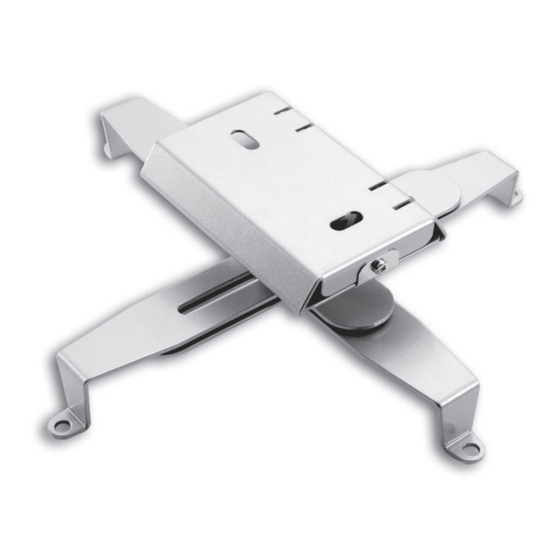
General instructions
After fixing the mounting kit the distance between the ceiling
and the projector bottom is approx. 7.5 cm.
The distance between the drill-holes on your projector for
fixing the mounting kit must be between 120 mm and 350 mm.
The projector can be fastened to only 3 carrying arms
(sometimes to only 2 – then use the 2 other arms as support).
Due its joint the holding plate can be tilted by ± 12° and
rotated by ± 180°.
Preparation
First choose the location of the ceiling fixture with the projec-
tor in accordance with the projection distance and the position
of the lens!
If in doubt, test the projection.
Provide the proper material and tools for fixing the mounting
plate
1
on the ceiling.
For fixing the projector you need 2 spanners SW10 and a Phil-
lips screw driver.
Mounting
Loosen the safety screw, take off the mounting plate
the unit and fix it at the proper location with suitable screws
and plugs.
Put your projector upside down on a soft surface.
Adjust the variable carrying arms of the holder
position of the drill-holes on the projector body, and fasten
the projector by inserting the screws (M3, M4 or M5) into the
drill-holes.
Check the stability of the construction!
Attach the mains and the wiring, and push the projector holder
with the projector into the pre-mounted mounting plate until it
engages.
Secure the construction by fixing the safety screw on the
mounting plate.
Advice:
For exact adjustment you should be able to move the upper part
of the projector holder.
If the joint is too tight or too loose, you can manipulate the
clamp with a spanner.
As the remote control usually switches to stand-by when the
projector is not in use, we recommend you to equip the mains
with an additonal on/off switch.
If the drill-holes on the projector body are not level, a height
difference of max. 8 mm can be compensated by re-arranging
the carrying arms.
Informations générales
La distance entre le plafond et le socle du projecteur est de 7,5
cm. Le domaine d'attaches de votre projecteur doit être entre
120 mm et 350 mm.
Une fixation avec 3 bras uniquement est possible – dans certains
cas également avec 2 bras. Dans ce cas, utiliser les deux autres
bras en tant que soutient.
L'articulation du montage plafond a une articulation qui vous
permet un inclinement de ± 12° dans toutes les directions et de
tourner le projecteur à ± 180°.
Préparations
Vérifier tout d'abord le positionnement du montage plafond
selon la distance à l'écran et la position de l'objectif par rapport
au centre de l'écran.
En cas de doute, faire un test de projection.
Acheter le matériel nécessaire pour la fixation du montage
plafond
1
au plafond, adapté au matériel de votre plafond.
Pour la fixation du projecteur, vous avez également besoin de 2
clés ouvertes SW10 et un tourne-vis croix.
Montage
1
from
Dévisser puis retirer la vis de sécurité de la plaque plafond
fixer cette plaque avec les vis et chevilles appropriées à l'endroit
souhaité au plafond.
Poser votre projecteur (partie inférieure sur le dessus) sur une
2
to the
surface douce. Positioner les bras du montage plafond
les points d'attaches de votre projecteur et les fixer avec les sets
de vis livrés (M3, M4 ou M5).
Vérifier la stabilité de cette fixation.
Brancher le câble de tension ainsi que le(s) câble(s) vidéo /
informatique et insérer le porte-projecteur et le projecteur
jusqu'à la butée de la plaque-plafond. Visser la vis de sécurité du
porte-projecteur à la plaque plafond.
Attention !
Pour le réglage précis de la projection, l'articulation doit être
mobile. Si cette partie est trop mobile ou trop dure, vous pouvez
le régler à l'aide des deux clés ouvertes.
Puisque le télécommande du projecteur, en cas de non-utilisation,
ne premet que la mise en veille, nous recommandons l'utilisation
d'un interrupteur séparé.
Des hauteurs différentes des trous d'attache du projecteur
peu-vent être compensées jusqu'à 8 mm en échangeant les
quatre bras.
7419 000 000 D/GB/F 2014-06 / 843 898
Änderungen vorbehalten / Subject to alterations / Modifications réservées
Kindermann GmbH · Mainparkring 3 · D-97246 Eibelstadt
E-Mail: info@kindermann.de · www.kindermann.com
Home Cinema CT
Nr. 7419 000 000
Bedienungsanleitung
Operating instructions
et
1
Mode d´emploi
selon
2
D
GB
Printed in Germany
F
06.2014

Manuels Connexes pour Kindermann Home Cinema CT

Sommaire des Matières pour Kindermann Home Cinema CT
- Page 1 8 mm can be compensated by re-arranging the carrying arms. 7419 000 000 D/GB/F 2014-06 / 843 898 Printed in Germany Änderungen vorbehalten / Subject to alterations / Modifications réservées Kindermann GmbH · Mainparkring 3 · D-97246 Eibelstadt 06.2014 E-Mail: info@kindermann.de · www.kindermann.com...
- Page 2 Zeichenerklärung / Lieferumfang Generelle Erläuterungen Sicherheitshinweise Legend / Materiel supplied Bei installierter Halterung beträgt die Höhe von Decke bis • Überzeugen Sie sich in jedem Fall von der ausreichenden Explication du schéma / Matériel livré Projektor-Unterseite ca. 7,5 cm. Tragfähigkeit der Deckenkonstruktion und benutzen Sie Schrauben und Dübel, die für die vorhandene Deckenstruktur Der Befestigungsbereich der Gewindebohrungen in Ihrem geeignet sind.