Table des Matières
Publicité
Les langues disponibles
Les langues disponibles
Liens rapides
Publicité
Table des Matières

Manuels Connexes pour CDVI Centrale Mifare DGM1D


Sommaire des Matières pour CDVI Centrale Mifare DGM1D
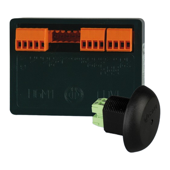
- Page 1 FRANCAIS ENGLISH DGM1D Centrale Mifare 1 porte ® 1-Door Mifare controller/reader system ® Range: Integrated Access Control / Gamme: Contrôle d’Accès Intégré INSTALLATION MANUAL MANUEL D’INSTALLATION Group Products...
-
Page 2: Presentation Du Produit
VIGIK ) et au maximum à 10 mètres interphonique ou sensible, il est recommandé ® (pour l’accord d’antenne). d’utiliser le câblage coaxial (Câble inférieur - La tête utilisée comporte un connecteur 4 broches. comme supérieur à 2 mètres). cdvi.com cdvigroup.com... -
Page 3: Montage
- Mettre en place le cavalier JP2, - Rétablir l’alimentation ; le voyant de la centrale s’allume (rouge fi xe) ; quand il commence à clignoter, cela indique que l’élimination est intervenue, - Couper à nouveau l’alimentation, - Retirer le cavalier JP2, cdvi.com cdvigroup.com... -
Page 4: Kit De Montage
Commun Led V Connection Led verte Bouton poussoir de sortie BUS RS 485 Contact relais normalement ouvert BUS RS 485 Commun relais Liaison PCV123D Contact relais normalement connecté Liaison PCV123D Alimentation 12V AC/DC Liaison PCV123D Alimentation 12V AC/DC cdvi.com cdvigroup.com... -
Page 5: Alimentation
La varistance limite les surtensions provoquées par le bobinage A la mise sous tension le voyant de l’antenne de la gâche – effet de self. doit s’allumer orange pendant 4 secondes vérifi ant le bon raccordement de l’antenne. cdvi.com cdvigroup.com... -
Page 6: Exemple D'installation Avec Interface Bus (Intbusdgm1D)
Contact relais normalement ouvert Commun relais Câble recommandé : Contact relais normalement connecté 1 câble 2 paires SYT1 blindé 8/10ème. Alimentation 12V AC/DC Utilisez 1 paire pour l’alimentation et 1 paire Alimentation 12V AC/DC pour la transmission des données. cdvi.com cdvigroup.com... - Page 7 Datas vers centrale exterieur Bouton poussoir intérieur Masse commune ( P1 et P2 ) Commun voyants (Non utilisé) Bouton poussoir extérieur Voyant Vert (Non utilisé) Contact fermeture porte, N.C. (Porte fermée) Voyant Rouge (Non utilisé) et N.O. (Porte ouverte) cdvi.com cdvigroup.com...
-
Page 8: Exemple D'installation Avec Interface Bus Wiegand (Intbusw)
8/10ème ou coaxial (Utiliser Commun 1 paire pour l’alimenation Bouton poussoir de sortie et 1 paire pour la transmission des données). Contact relais normalement ouvert Commun relais Tête de lecture Contact relais normalement connecté Alimentation 12V AC/DC Alimentation 12V AC/DC cdvi.com cdvigroup.com... - Page 9 12 V DC uniquement (Confi guration usine) Câble de blindage Coupez le strap Si vous ne souhaitez 12 V AC ou 24 V DC pas de gestion de l’etat Vers d’autres contrôleur porte : Relier E et M de portes (INTBUSW) cdvi.com cdvigroup.com...
- Page 10 Liaison PCV123D Liaison PCV123D Liaison PCV123D BUS RS 485 BUS RS 485 Bouton poussoir de sortie Bouton poussoir de sortie Commun DATAS Datas vers centrale exterieur Led V Connection Led verte Led R Connection Led rouge Antenne DGM1D Antenne cdvi.com cdvigroup.com...
- Page 11 à la condition, qu’il soit installé conformément aux préconisations du fabricant et qu’il n’y ait pas eu d’interventions ou de modifi cations sur le produit. La responsabilité de CDVI se limite à la réparation ou à l’échange du produit. CDVI n’assume aucune responsabilité concernant les dommages sur les biens ou les personnes.
-
Page 12: General Information
- Distance between the controller and the reader or a sensitive device, it is recommended to should not exceed 2 meters with AWG35 cable use a coaxial cabling (less or more than 2 meters). and 10 meters with a coaxial cable. cdvi.com cdvigroup.com... - Page 13 LED starts fl ashing in red, - Turn off again the power on the controller, - Remove jumper JP2, - Turn on the power supply; the controller is ready to be reprogrammed, cdvi.com cdvigroup.com...
-
Page 14: Mounting Kit
Led R Red LED Ground Led V Green LED Push button input BUS RS 485 Normally open relay output BUS RS 485 Common relay output PCV123D Link Normally close relay output PCV123D Link 12V AC/DC PCV123D Link 12V AC/DC cdvi.com cdvigroup.com... - Page 15 When the controller is powered, the orange led on the reader electromagnetic fi elds do not forget to mount the varistor in parallel must light on during 4 seconds. After that, the led on the on the lock. reader switches off. cdvi.com cdvigroup.com...
- Page 16 N.O. relay output Recommended cable: Common relay output AWG35 2 pair shielded cable. NC relay output Use 1 pair cable to power the controller and Input voltage 12V AC/DC another pair for the data transmission. Input voltage 12V AC/DC cdvi.com cdvigroup.com...
- Page 17 Datas to external centrol unit Request to exit input Common ground (P1 and P2) Common lights (Not used) Request to enter input Green light (not used) Door contact, NC (Door closed) Red light (Not used) and NO (Door open) cdvi.com cdvigroup.com...
- Page 18 Request to exit input (Push button) 8/10ème or coaxial (Use Ground 1 pair to power and 1 pair data). Request to exit input (Push button) N.O. relay output Common relay output Reader NC relay output Input voltage 12V AC/DC Input voltage 12V AC/DC cdvi.com cdvigroup.com...
- Page 19 (Refer to INTBUSW manual) Strike Magnetic lock Varistor SYT1wire shielded 12 V DC only (Default confi guration) Wire shielded Cut the strap 12 V AC or 24 V DC EM Input To th next reader (Door status) controller cdvi.com cdvigroup.com...
- Page 20 PCV123D link PCV123D link RS485 BUS RS485 BUS Request to exit input (Push button) Request to exit input (Push button) Ground DATAS Data to external control unit Led V Green led Led R Red Led Antenna DGM1D Antenna cdvi.com cdvigroup.com...
- Page 21 “Limited Lifetime Warranty”, complete the enclosed registration card and return it, either by e-mail or post, to the relevant CDVI address or completion of the on line registration at www.cdvigroup.com. Repair or replacement of the defective product is the exclusive remedy.
- Page 22 INSTALLATION MANUAL DGM1D 1-Door Mifare controller/reader system ® 8] NOTES cdvi.com cdvigroup.com...
- Page 23 INSTALLATION MANUAL DGM1D 1-Door Mifare controller/reader system ® cdvi.com cdvigroup.com...
- Page 24 Reference : G0301FR0424V02 Extranet : EXE-CDVI_IM DGM1D CMYK A5 EN-FR 02 Creator of electronic access solutions *G0301FR0424V02* CDVI Group FRANCE (Headquarter/Siège social) Phone: +33 (0)1 48 91 01 02 Fax: +33 (0)1 48 91 21 21 CDVI CDVI CDVI CDVI UK...