Table des Matières

Publicité

Les langues disponibles
  • FR

Les langues disponibles

Liens rapides

D
Gebrauchs- und Montageanweisung
Induktions-Glaskeramik-Kochfeld
GB
Instructions for fi tting and use
Glass ceramic induction hob
F
Instructions de montage et d'utilisation
Table de cuisson vitrocéramique à induction
I
Istruzioni per uso e montaggio
Piano di cottura ad induzione in vetroceramica
NL
Gebruiks- en montageaanwijzing
Keramische inductiekookplaat
CTDI K 940C NE

Publicité

Table des Matières
loading

Sommaire des Matières pour Bauknecht CTDI K 940C NE

  • Page 1 Instructions for fi tting and use Glass ceramic induction hob Instructions de montage et d’utilisation Table de cuisson vitrocéramique à induction Istruzioni per uso e montaggio Piano di cottura ad induzione in vetroceramica Gebruiks- en montageaanwijzing Keramische inductiekookplaat CTDI K 940C NE...
  • Page 2: Table Des Matières

    KNECHT GEKAUFT HABEN 4.14 Kochfeld abschalten ..........19 4.15 STOP-Funktion ...........20 Für einen umfassenderen Kundenservice, registrieren Sie 4.16 Recall-Funktion ...........20 Ihr Produkt bitte unter www.bauknecht.eu/ 4.17 Verriegelung ............21 Lesen Sie unbedingt die Sicherheitshinweise vor der Inbe- 4.18 Brückenfunktion ..........21 triebnahme Ihres Gerätes.
  • Page 3: Sicherheits- Und Warnhinweise

    Beschädigungen an der Glas- WICHTIG fl äche besteht bei Gebrauch Stromschlagge- Lesen und laden Sie die komplette Anleitung fahr. unter docs.bauknecht.eu runter oder rufen ACHTUNG: Feuergefahr! Die Kochzonen Sie die in der Garantieerklärung aufgeführte dürfen nicht als Ablagefl äche benutzt werden. Telefonnummer an.
  • Page 4: Reinigung Und Wartung

    Sicherheits- und Warnhinweise INSTALLATION REINIGUNG UND WARTUNG Das Gerät muss immer von mindestens zwei ACHTUNG: Trennen Sie vor Reinigung und Personen bewegt und eingebaut werden - Instandhaltung das Gerät von der Stromver- Unfallgefahr!. Tragen Sie beim Auspacken sorgung; niemals Dampfreinigungsgeräte und Einbau Schutzhandschuhe zur Vermei- verwenden - Stromschlaggefahr.
  • Page 5: Tipps Zum Energiesparen

    Sicherheits- und Warnhinweise TIPPS ZUM ENERGIESPAREN VERPACKUNGSENTSORGUNG • Schalten Sie die Haube nur mit minimaler Ge- • Das Verpackungsmaterial ist zu 100% wie- schwindigkeit ein, wenn Sie mit dem Kochen derverwertbar und trägt das Recycling-Sym- beginnen und lassen Sie sie nur ein paar .
  • Page 6: Montageanleitung

    Montageanleitung 2 Montageanleitung 2.3 Einbau Wichtige Hinweise 2.1 Sicherheitshinweise für den Küchenmöbelmonteur • Übermäßige Hitzeentwicklung von unten z.B. von ei- • Das Gerät muss immer von mindestens zwei Personen nem Backofen ohne Querstromlüfter ist zu vermeiden. bewegt und eingebaut werden - Unfallgefahr! Tragen Sie beim Auspacken und Einbau Schutzhandschuhe •...
  • Page 7: Variable Einbaumöglichkeit: Aufl Iegender Einbau

    Montageanleitung 2.4 Variable Einbaumöglichkeit: aufl iegender 2.5 Variable Einbaumöglichkeit: fl ächenbündiger Einbau Einbau Maße in mm 904+1 880+1 880+1 min.50 min.50 min.50 min.50 Dichtband in die Ecke der Aufl agekante der Arbeitsplatte aufkleben, so dass sich kein Silikonkleber unter das Koch- Mindestabstand zu benachbarten Wänden feld durchdrücken kann.
  • Page 8: Abbildungen Küchenschrank

    Montageanleitung 2.6 Abbildungen Küchenschrank Arbeitsplatte 700 mm optional Kohlefi lter max.430 ≥335 ≥170 max.430 NW150 max.300 Abluftauslass links Abluft wahlweise links oder rechts: Die Abluft kann je nach Einbausituation links oder rechts gewählt Abluftauslass rechts werden. Beachten Sie bitte hierzu die nebenste- henden Maße zur optimalen Planung.
  • Page 9: Arbeitsplattenausschnitt Herstellen

    Montageanleitung 2.7 Arbeitsplattenausschnitt herstellen • Verkleben Sie die Kochfl äche nur an ihren Außenrän- dern! Der Ausschnitt wird in zwei Arbeitsschritten hergestellt. • Nie die Kochfl äche mit der Glaskeramik ungeschützt 1. Den Ausschnitt für die Bodenwanne herstellen. auf die Arbeitsplatte oder den Boden legen. Durch Ver- 2.
  • Page 10 Montageanleitung Wandmontage Inselmontage...
  • Page 11: Zusammenbau Abluftsystem

    Montageanleitung 2.9 Zusammenbau Abluftsystem Abluftkanal-Komponenten (optional) Die Verbindung zwischen Kochfeld und Lüfter kann mit einem Flexschlauch oder einem Flachkanal erfolgen. Den Flachkanal nach Bedarf in der Länge mit einer Fein- säge kürzen. Zu Punkt c Das fl exible Verbindungsstück wird bei einer Arbeitsplat- tentiefe von 600 mm verwendet.
  • Page 12: Wichtige Hinweise Zum Einbau Des Kochmuldenlüfters

    Montageanleitung 2.10 Wichtige Hinweise zum Einbau des Koch- • Die Nennweite der Umluftrohre darf 150 mm nicht unterschreiten. muldenlüfters • Abluftleitungen sollen so kurz wie möglich sein, nicht • Das Gerät muss immer von mindestens zwei Personen im 90 Grad-Winkel sondern in weichen Bögen geführt bewegt und eingebaut werden - Unfallgefahr! Tragen werden und keine Querschnittsreduzierungen haben.
  • Page 13: 7-Poliger Stecker Anschluss Lüfter

    Montageanleitung 2.11 7-poliger Stecker Anschluss Lüfter WARNUNG VOR ELEKTRISCHER Vorgehensweise ENERGIE! ES BESTEHT LEBENSGEFAHR! Für den Lüfteranschluss verbinden Sie die beiden 7-poli- gen Stecker. In der Nähe dieses Symbols sind span- nungsführende Teile angebracht. Abdeckun- Steckersicherung am 7 poligen Stecker (Lüfter) des Koch- feldes öff...
  • Page 14: Technische Daten

    Montageanleitung Anschlusswerte 2.13 Technische Daten Netzspannung: 380-415V 3N~, 50/60Hz Abmessungen Kochfeld Komponentennennspannung: 220-240V Höhe/ Breite/ Tiefe ..mm 200 x 900 x 580 Anschlussleitung werkseitig vorhanden Kochzonen • Das Kochfeld ist werkseitig mit einer temperaturbestän- alle ......cm / kW 19x22/ 2,2 (3,7)* digen Anschlussleitung ausgestattet.
  • Page 15: Gerätebeschreibung

    Gerätebeschreibung 3 Gerätebeschreibung Sensorfeld für Sensorfeld für Kochzone vorne Kochzone hinten Das Dekor kann von den Abbildungen abweichen. 10. Kochstufen-Anzeige 1. Induktionskochzone vorne 11. Verriegelungs-Taste 2. Induktionskochzone hinten 12. Warmhalte-Taste 3. Glaskeramik-Kochfeld 13. Anzeige der Warmhaltestufe (3 Stufen) 4. Touch-Control Bedienfeld 14.
  • Page 16: Bedienung Durch Sensortasten

    Gerätebeschreibung 3.1 Bedienung durch Sensortasten 3.2 Wissenswertes zum Slider (Sensorfeld) Die Bedienung des Glaskeramik-Kochfeldes erfolgt durch Der Slider funktioniert grundsätzlich wie die Sensortasten, Touch-Control Sensortasten. Die Sensortasten funktio- mit dem Unterschied, dass der Finger auf der Glaskera- nieren wie folgt: mit der Fingerspitze ein Symbol auf der mikoberfl...
  • Page 17: Bedienung

    Bedienung 4 Bedienung 4.3 Betriebsdauerbegrenzung Das Induktionskochfeld besitzt eine automatische Be- 4.1 Das Induktionskochfeld triebsdauerbegrenzung. Die Kochfl äche ist mit einem Induktionskochfeld ausgestat- Die kontinuierliche Nutzungsdauer jeder Kochzone ist tet. Eine Induktionsspule unterhalb der Glaskeramik-Koch- abhängig von der gewählten Kochstufe (siehe Tabelle). fl...
  • Page 18: Geschirr Für Induktionskochfeld

    Bedienung 4.6 Geschirr für Induktionskochfeld 4.7 Energiespartipps Das für die Induktionskochfl äche benutzte Kochgefäß Nachfolgend fi nden Sie einige wichtige Hinweise, um ener- muss aus Metall sein, magnetische Eigenschaften haben giesparend und effi zient mit Ihrem neuen Induktionskoch- und eine ausreichende Bodenfl äche besitzen. feld und dem Kochgeschirr umzugehen.
  • Page 19: Gerät Betriebsbereit Schalten

    Bedienung 4.10 Gerät betriebsbereit schalten Mit der Stand-by Taste wird das Gerät betriebsbereit geschaltet. Die Taste ist sozusagen der Hauptschalter. Es erfolgt zuerst ein Selbst-Test der Steuerung und die Anzeigen leuchten kurz auf. Nach dem Ausschalten über diese Taste bleibt das Gerät noch ca.
  • Page 20: Stop-Funktion

    Bedienung 4.15 STOP-Funktion Der Kochvorgang kann kurzzeitig durch die STOP-Funk- tion unterbrochen werden, z.B. wenn es an der Haustüre klingelt. Um den Kochvorgang mit den gleichen Kochstu- fen fortzusetzen, muss die STOP-Funktion aufgehoben werden. Ein evtl. eingestellter Timer wird angehalten und läuft danach weiter.
  • Page 21: Verriegelung

    Bedienung 4.17 Verriegelung Die Verriegelung soll verhindern, dass Kinder versehent- lich oder absichtlich das Induktionskochfeld einschalten. Dazu wird die Bedienung gesperrt. Verriegelung einschalten 1. Die Ein-/Aus-Taste Kochfeld betätigen (ca. 1 Sek.), um das gesamte Kochfeld einzuschalten. 2. Gleich darauf die Verriegelungs-Taste und die STOP-Taste gleichzeitig betätigen.
  • Page 22: Abschaltautomatik (Timer)

    Bedienung 4.19 Abschaltautomatik (Timer) Durch die Abschaltautomatik wird jede eingeschaltete Koch- zone nach einer einstellbaren Zeit automatisch abgeschaltet. Es können Kochzeiten von 10 Sek. (0.10) bis 1 Std. 59 Min. (1.59) eingestellt werden. 1. Das Kochfeld einschalten. Eine oder mehrere Kochzonen einschalten und gewünschte Kochstufen wählen.
  • Page 23: Ankochautomatik

    Bedienung 4.21 Ankochautomatik Bei der Ankochautomatik erfolgt das Ankochen mit Koch- stufe 9. Nach einer bestimmten Zeit wird automatisch auf eine geringere Fortkochstufe (1 bis 8) zurückgeschaltet. Bei Anwendung der Ankochautomatik muss lediglich die Fortkochstufe gewählt werden, mit der das Gargut weiter- gegart werden soll, weil die Elektronik selbständig zurück- schaltet.
  • Page 24: Verriegelung

    Bedienung 4.23 Verriegelung Durch die Verriegelung kann die Bedienung der Tasten und die Einstellung einer Kochstufe gesperrt werden. Lediglich die Ein-/Aus-Taste bleibt zum Ausschalten des Kochfeldes bedienbar. Verriegelung einschalten 1. Die Verriegelungs-Taste betätigen. Die LED über der Verriegelungstaste leuchtet. Verriegelung ausschalten 2.
  • Page 25: Lüfter Verwenden

    Bedienung 4.26 Lüfter verwenden In der Mitte des Kochfeldes befi ndet sich der Lüfter mit dem Abzug nach unten. Vor Inbetriebnahme des Lüfters Glas-Abdeckung vollständig abnehmen. Bei Modellen mit off ener Abdeckung ist ein Abneh men nicht erforderlich. Glas-Abdeckung Wichtig: Die off...
  • Page 26: Reinigung Und Pfl Ege

    Reinigung und Pfl ege 5 Reinigung und Pfl ege Eventuell die Reinigung mehrmals wiederholen. Durch die Ver- wendung aggressiver Reinigungsmittel und durch scheuernde • Vor dem Reinigen das Kochfeld ausschalten und abkühlen Topfböden wird das Dekor mit der Zeit abgeschmirgelt und es lassen.
  • Page 27: Was Tun Bei Problemen

    Was tun bei Problemen? 6 Was tun bei Problemen? Das Topfzeichen erscheint weiter, obwohl ein Koch- gefäß aufgesetzt wurde? Unqualifi zierte Eingriff e und Reparaturen am Gerät sind gefährlich, weil Stromschlag- und Kurzschlussgefahr Das Kochgefäß ist für Induktion ungeeignet oder es hat besteht.
  • Page 28 4.14 Switching off the hob ...........45 4.15 Stop function ............46 4.16 Recall function ............46 4.17 Control panel lock ..........47 THANK YOU FOR BUYING A BAUKNECHT PRODUCT 4.18 Bridging function ..........47 4.19 Automatic switch-off (timer) .........48 In order to receive a more complete assistance, please 4.20 Minute minder (egg timer) ........48...
  • Page 29: Safety Instructions And Warnings

    Download the complete instruction manual on WARNING: Unattended cooking on a hob with docs.bauknecht.eu or call the phone number or oil can be dangerous – risk of fi re. NEVER shown on the warranty booklet. try to extinguish a fi re with water, but switch Before using the appliance, read these safety off...
  • Page 30: Electrical Warnings

    Safety instructions and warnings INSTALLATION ELECTRICAL WARNINGS The appliance must be handled and installed It must be possible to disconnect the applian- by two or more persons - risk of injury. Use ce from the power supply by unplugging it if protective gloves to unpack and install - risk of plug is accessible, or by a multi-pole switch in- cuts.
  • Page 31: Disposal Of Packaging Materials

    Safety instructions and warnings DISPOSAL OF PACKAGING MATERIALS ENERGY SAVING TIPS • The packaging material is 100% recyclable • Switch ON the hood at minimum speed when and is marked with the recycle symbol you start cooking and kept it running for few .
  • Page 32: Instructions For Assembly

    Instructions for assembly 2 Instructions for assembly 2.3 Installation Important information 2.1 Safety instructions for kitchen unit fi tters • Avoid excessive thermal development from below e.g. • The appliance must be handled and installed by two or from a baking oven without a cross fl ow cooling device. more persons - risk of injury.
  • Page 33: Variable Installation Possibilities: Overlying Installation

    Instructions for assembly 2.4 Variable installation possibilities: 2.5 Variable installation possibilities: Overlying installation Flush installation Dimensions in mm 904+1 880+1 880+1 min.50 min.50 min.50 min.50 Glue the sealing tape onto the corner of the supporting Minimum distance to adjacent walls edge of the worktop so that no silicone adhesive can be Opening dimensions pressed under the hob.
  • Page 34: Illustrations Kitchen Cupboard

    Instructions for assembly 2.6 Illustrations kitchen cupboard. 700-mm worktop optional carbon fi lter max.430 ≥335 ≥170 max.430 max.300 NW150 Exhaust outlet on the left Option of outgoing air on the left or right: Depending on installation, left or right can be chosen for outgoing Exhaust outlet on the right air Please note the dimensions shown opposite for optimal planning.
  • Page 35: Making The Worktop Recess

    Instructions for assembly 2.7 Making the worktop recess • Only glue the hob on its outer edges! • Never place the hob with the glass ceramic surface un- The cut-out is produced in two work steps. protected on the worktop or the fl oor. Dirt (metal chips, 1.
  • Page 36 Instructions for assembly Wall installation Island installation...
  • Page 37: Extraction Air System Assembly

    Instructions for assembly 2.9 Extraction air system assembly Exhaust air duct components (optional): The hob and the fan can be connected with a fl exible hose or a fl at duct. Shorten the fl at duct with a fi ne saw if necessary. Option fl...
  • Page 38: Important Notes For Fi Tting

    Instructions for assembly 2.10 Important notes for fi tting • Exhaust air pipes should be as short as possible. They should not have a 90-degree angle; instead they should • The appliance must be handled and installed by two or have soft bends and no reductions in their cross-secti- more persons - risk of injury.
  • Page 39: 7-Pole Fan Plug Connector

    Instructions for assembly 2.11 7-pole fan plug connector Procedure WARNING OF ELECTRICAL ENERGY! Connect the two 7-pole plus for the fan connection. RISK OF FATAL INJURY! Open the plug retainer on the 7-pole plug (fan) of the hob Live components have been installed and attach the 7-pole fan mating connector (e) until it is near this symbol.
  • Page 40: Technical Data

    Instructions for assembly Power supply 2.13 Technical Data Mains voltage: 380-415V 3N~, 50/60Hz Hob dimensions Component rated voltage: 220-240V height/ width/ depth ...mm 200 x 900 x 580 Mains cable available in the factory Cooking zones • The hob has been fi tted with a temperature-resistant all zones ....cm / kW 19x22/ 2,2 (3,7)* connection cable in the factory.
  • Page 41: Appliance Description

    Appliance description 3 Appliance description Sensor fi eld for Sensor fi eld for Front cooking zone Rear cooking zone 10. Power setting display The decorative design may deviate from the illustrations. 11. Lock key 1. Front induction cooking zone 12. Warming key 2.
  • Page 42: Operating The Hob With The Sensor Keys

    Appliance description 3.1 Operating the hob with the sensor keys 3.2 Worth knowing about the slider (sensorfi eld) The glass ceramic hob is operated with touch control sen- In principle, the slider functions the same as the touch sor keys. The sensor keys are operated as follows: lightly controls;...
  • Page 43: Operation

    Operation 4 Operation 4.3 Operation time limit The induction hob has an automatic time limit function. 4.1 The induction hob The duration of continuous use of each cooking zone de- The hob is equipped with an induction cooking mode. An pends on the cooking level selected (see chart).
  • Page 44: Cookware For Induction Hobs

    Operation 4.6 Cookware for induction hobs 4.7 How to cut power consumption Cookware for induction cooking zones must be made of The following are a few useful hints to help you cut your metal and have magnetic properties. The base must be consumption of energy and use your new induction hob suffi...
  • Page 45: Switching The Appliance Into The Standby Mode

    Operation 4.10 Switching the appliance into the standby mode This standby key is used to switch the entire hob operatio- nal. It is, as it were, the main switch. An automatic test of the controls will be carried out fi rst of all, and the displays will light up briefl...
  • Page 46: Stop Function

    Operation 4.15 Stop function The cooking process can be briefl y interrupted with the STOP function, e.g. if the doorbell rings. The STOP func- tion must be released in order to continue cooking at the same power level. If a timer has been set it will pause and will then continue.
  • Page 47: Control Panel Lock

    Operation 4.17 Control panel lock The control panel lock serves the purpose of preventing children from switching on the induction hob either acci- dentally or intentionally. The controls are blocked here. Switching on the control panel lock 1. Press the ON/OFF key of the hob (approx.
  • Page 48: Automatic Switch-Off (Timer)

    Operation 4.19 Automatic switch-off (timer) The automatic switch-off device is used to automatically switch off any cooking zone after an adjustable period of time. Coo- king times ranging from 10 seconds (0.10) to 1 hour and 59 minutes (1.59) can be set. 1.
  • Page 49: Automatic Boost Function

    Operation 4.21 Automatic boost function Food is parboiled at power setting 9 with the automatic boost function. After a certain time, the power level will switch down automatically to a lower simmering setting (1 to 8). When using the automatic boost function only the sim- mering setting with which the food is to be cooked through needs to be selected since the electronic unit switches down automatically.
  • Page 50: Locking

    Operation 4.23 Locking The lock can be used to lock key operation and cooking level settings. Only the ON/OFF key can be used to switch the hob off . Activating the lock 1. Press the lock key . The control lamp above the Lock key will light up.
  • Page 51: Using The Fan

    Operation 4.26 Using the fan The fan is located in the middle of the hob with the extractor facing downwards. Remove the glass cover before initial operation of the fan. The cover does not need to be removed from models with an open cover.
  • Page 52: Cleaning And Care

    Cleaning and care 5 Cleaning and care agents. You may need to repeat the cleaning process several times. In time, the decoration will wear off and dark • Switch the hob off and let it cool down before you clean stains will appear as a result of using aggressive cleaning agents and faulty pan bases.
  • Page 53: What To Do If Trouble Occurs

    What to do if trouble occurs? 6 What to do if trouble occurs? The pot sign appears? Interference with and repairs to the appliance by unquali- A cooking zone has been switched on and the hob is ex- fi ed persons are dangerous as they can result in an elec- pecting a suitable pot or pan to be placed on the cooking tric shock or a short circuit.
  • Page 54 4.12 Mettre en marche la table de cuisson Afi n de bénéfi cier d'un service après-vente complet, veuil- et la zone de cuisson ..........71 lez enregistrer votre produit à l'adresse www.bauknecht. 4.13 Arrêter la zone de cuisson ........71 eu/register 4.14 Arrêter la table de cuisson ........71 4.15 Fonction STOP ...........72...
  • Page 55: Consignes De Sécurité Et Avertissements

    ATTENTION : La préparation des plats avec Lisez et téléchargez le mode d'emploi entier de la graisse ou de l'huile doit toujours se à l'adresse docs.bauknecht.eu ou appelez faire sous surveillance - Risque d'incendie. le numéro de téléphone mentionné dans la Ne jamais éteindre les feux de graisse avec...
  • Page 56: Utilisation Conforme

    Consignes de sécurité et avertissements INSTALLATION UTILISATION CONFORME L’appareil doit toujours être déplacé et PRUDENCE : L'appareil ne doit pas être encastré par au moins deux personnes - commandé par l'intermédiaire d'appareils de risque d’accident ! Lors du déballage et de commutation externes, comme minuteries ou l’encastrement, portez toujours des gants de télécommande séparée.
  • Page 57 Consignes de sécurité et avertissements NETTOYAGE ET MAINTENANCE REMARQUES CONCERNANT LES ÉCONOMIES D’ÉNERGIE ATTENTION : Avant toute intervention de net- toyage et de maintenance, coupez l'appareil • Mettre en route la hotte uniquement à allure du réseau électrique ; ne jamais utiliser de minimum lorsque vous commencez la cuisson nettoyeurs à...
  • Page 58: Instructions De Montage

    Instructions de montage 2 Instructions de montage 2.3 Montage Consignes importantes 2.1 Consignes de sécurité pour l’installateur des meubles de cuisine • Éviter toute production de chaleur excessive sous la table de cuisson, provenant par exemple d'un four sans • L’appareil doit toujours être déplacé...
  • Page 59: Possibilités Variables De Montage : Montage Posé

    Instructions de montage 2.4 Possibilités variables de montage : 2.5 Possibilités variables de montage : Montage posé Montage posé 904+1 Dimensions en mm 880+1 880+1 min.50 min.50 min.50 min.50 Coller le ruban d’étanchéité dans l’angle de la découpe du plan de travail et ce, de telle sorte que la colle silicone ne Espacement minimal par rapport aux meubles puisse pas pénétrer sous la table de cuisson.
  • Page 60: Illustrations Armoire De Cuisine

    Instructions de montage 2.6 Illustrations Armoire de cuisine Plan de travail 700 mm fi ltre à charbon en option ≥335 max.430 ≥170 max.430 NW150 max.300 Sortie d'évacuation d'air à gauche Évacuation d'air au choix à gauche ou à droite : en fonction de la situation de montage, la position de l'évacuation d'air peut être à...
  • Page 61: Réaliser La Découpe Dans Le Plan De Travail

    Instructions de montage 2.7 Réaliser la découpe dans le plan de travail • Ne collez la table de cuisson que sur ses bords extérieurs! • Ne jamais poser la table de cuisson sur le plan de travail La découpe est réalisée en deux étapes. ou par terre, le côté...
  • Page 62 Instructions de montage Montage mural Montage à 'île...
  • Page 63: Assemblage Du Système D'évacuation D'air

    Instructions de montage 2.9 Assemblage du système d'évacuation d'air Composants du canal d'évacuation (option) : Le raccordement de la table de cuisson au ventilateur peut se faire avec une gaine fl exible ou un canal plat. Raccourcir le cas échéant avec une scie fi ne la longueur du canal plat.
  • Page 64: Instructions Importants De Montage

    Instructions de montage que possible, ne pas présenter d‘angles à 90°, mais des 2.10 Instructions importants de montage coudes d‘une angulation supérieure, ni de réductions du • L’appareil doit toujours être déplacé et encastré par au diamètre. moins deux personnes - risque d’accident ! Lors du dé- •...
  • Page 65: Connecteur 7 Pôles Raccordement Ventilateur

    Instructions de montage 2.11 Connecteur 7 pôles ATTENTION - ÉNERGIE ÉLECTRIQUE ! Raccordement ventilateur DANGER DE MORT ! Procédure Ce symbole est apposé à proximité de com- Relier les deux connecteurs 7 pôles pour raccorder le posants sous tension. Les couvercles munis ventilateur.
  • Page 66: Caractéristiques Techniques

    Instructions de montage Puissance connectée 2.13 Caractéristiques techniques Tension secteur : 380-415V 3N~, 50/60Hz Dimensions de la table de Tension nominale des composants: 220-240V cuisson Appareil livré avec cordon d’alimentation hauteur/ largeur/ profondeur mm 200 x 900 x 580 • La table de cuisson est équipée en usine d'un cordon Zones de cuisson électrique thermorésistant.
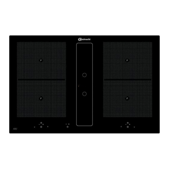
  • Page 67: Description De L'appareil

    Description de l’appareil 3 Description de l’appareil Champ sensitif pour Champ sensitif pour zone de cuisson avant zone de cuisson arrière Le décor peut être diff érent de celui illustré. 10. Affi chage position de cuisson 1. Zone de cuisson à induction avant 11.
  • Page 68: Commande Par Touches Sensitives

    Description de l’appareil 3.1 Commande par touches sensitives 3.2 Informations importantes concernant le Sli- der (champ sensitif) La commande de la table vitrocéramique se fait via les touches sensitives Touch-Control. Les touches sensitives Le Slider fonctionne toujours comme les touches fonctionnent de la manière suivante : effl...
  • Page 69: Utilisation

    Utilisation 4 Utilisation 4.3 Limitation de la durée de fonctionnement La table de cuisson à induction possède une limitation 4.1 La table de cuisson à induction automatique de la durée de fonctionnement. La table de cuisson est composée de zones de cuisson à La durée de fonctionnement en continu de chacune des induction.
  • Page 70: Vaisselle Pour Table De Cuisson À Induction

    Utilisation 4.6 Vaisselle pour table de cuisson à induction • Les autocuiseurs sont particulièrement économiques en terme de temps de cuisson et de consommation Le récipient utilisé avec la table à induction doit être en d’énergie, grâce à leur fermeture hermétique et la métal, avoir des propriétés magnétiques et posséder un surpression de vapeur à...
  • Page 71: Commuter L'appareil Prêt À L'emploi

    Utilisation 4.10 Commuter l'appareil prêt à l'emploi La touche Veille permet de placer l'appareil en mode prêt à l'emploi. Il s’agit du commutateur principal. Un autotest de la commande sera d'abord exécuté et les affi chages s'allument brièvement. Après l'arrêt de l'appareil avec cette touche, celui-ci reste encore en état de fonctionnement pendant encore 120 mi- nutes environ.
  • Page 72: Fonction Stop

    Utilisation 4.15 Fonction STOP Le déroulement de la cuisson peut être interrompu mo- mentanément à l’aide de la fonction STOP, p.ex. lorsque quelqu’un sonne à la porte. Pour continuer la cuisson avec les mêmes positions de cuisson, la fonction STOP doit être annulée.
  • Page 73: Verrouillage Des Touches Sensitives

    Utilisation 4.17 Verrouillage des touches sensitives La sécurité enfants évite que la table de cuisson à induction soit mise en marche involontairement ou volontairement par des enfants. Toute commande est bloquée. Activer le verrouillage des touches sensitives 1. Actionner la touche Marche/Arrêt de la table de cuisson (env.
  • Page 74: Arrêt Automatique (Minuterie)

    Utilisation 4.19 Arrêt automatique (minuterie) L’arrêt automatique permet d’arrêter automatiquement chaque zone de cuisson en fonctionnement après une durée de cuisson réglable. Vous pouvez régler des temps de cuisson entre 0.10 à 1.59 minutes. 1. Mettre en marche la table de cuisson. Mettre en marche une ou plusieurs zones de cuisson et sélectionner la(les) position(s) de cuisson souhaitée(s).
  • Page 75: Précuisson Automatique

    Utilisation 4.21 Précuisson automatique Avec la précuisson automatique, la précuisson se fait sur position 9. Après un certain temps, le réglage est ramené automatiquement sur une position inférieure (1 à 8) pour terminer la cuisson. En utilisant la précuisson automatique, il faut régler seule- ment la position de cuisson à...
  • Page 76: Verrouillage

    Utilisation 4.23 Verrouillage Le verrouillage permet de bloquer la commande des touches et le réglage d’une intensité de cuisson. Seule la touche Marche/Arrêt reste accessible pour couper la table de cuisson. Activer le verrouillage 1. Appuyer sur la touche de verrouillage .
  • Page 77: Utiliser Le Ventilateur

    Utilisation 4.26 Utiliser le ventilateur Le ventilateur, avec évacuation vers le bas, se trouve au centre de la table de cuisson. Retirer entièrement le couvercle en verre avant la mise en service du ventilateur. Le retrait n'est pas nécessaire pour les modèles avec couvercle ouvert en aluminium.
  • Page 78: Nettoyage Et Entretien

    Nettoyage et entretien 5 Nettoyage et entretien fonds rugueux peut endommager le décor et des taches sombres se forment. • Avant le nettoyage, éteignez la table de cuisson et laissez-la refroidir. 5.3 Ventilateur de table de cuisson • La table de cuisson en vitrocéramique ne doit, en aucun cas, Nettoyage du fi...
  • Page 79: Que Faire En Cas De Problèmes

    Que faire en cas de problèmes ? Après-Vente. 6 Que faire en cas de problèmes ? Le symbole de casserole s’affi che. Les interventions ou réparations non qualifi ées sont dangereuses ; elles peuvent provoquer une électrocuti- Une zone de cuisson a été mise en marche et elle attend on ou un court-circuit.
  • Page 80 4.15 Funzione Stop .............98 Per usufruire di un’assistenza clienti completa, si prega di 4.16 Funzione di richiamo ...........98 registrare il prodotto su www.bauknecht.eu/ register. 4.17 Blocco dei sensori ..........99 4.18 Funzione ponte ...........99 Leggere attentamente le istruzioni di sicurezza prima della 4.19 Spegnimento automatico (timer) .......100...
  • Page 81: Istruzioni Importanti Per La Sicurezza

    Non cercare mai di spegnere per mez- Leggere e scaricare le istruzioni complete su zo di acqua oli o grassi che bruciano (pericolo docs.bauknecht.eu o chiamare il numero di te- di esplosione!). Spegnere l'apparecchio e poi lefono indicato sulla dichiarazione di garanzia.
  • Page 82: Uso Consentito

    Istruzioni importanti per la sicurezza IAVVERTENZE ELETTRICHE È vietato riparare o sostituire parti dell’elett- Deve essere possibile staccare l’elettrodome- rodomestico, a meno che la riparazione o la stico dalla rete elettrica scollegando una spina sostituzione non siano esplicitamente descrit- accessibile o per mezzo di un interruttore a te nelle istruzioni per l’uso.
  • Page 83: Smaltimento Dell'imballo

    Istruzioni importanti per la sicurezza NOTE SUL RISPARMIO ENERGETICO La mancanza o la carenza di pulizia o il man- • Accendere la cappa soltanto ala velocità mini- cato rispetto delle avvertenze possono com- ma, quando si comincia a cucinare e lasciarla portare l’innesco di un fuoco.
  • Page 84: Istruzioni Di Montaggio

    Istruzioni di montaggio 2 Istruzioni di montaggio 2.3 Incasso 2.1 Indicazioni di sicurezza per il montaggio dei Avvertenze importanti mobili da cucina • Evitare un eccessivo surriscaldamento inferiore, causato per esempio da forni sprovvisti di ventilatore a • L’apparecchio deve essere movimentato e montato corrente trasversale.
  • Page 85: Possibilità Di Montaggio: Incasso Appoggiato

    Istruzioni di montaggio 2.4 Possibilità di montaggio: Incasso appoggiato 2.5 Possibilità di montaggio: Incasso per l’incas- so a paro Misure in mm 904+1 880+1 880+1 min.50 min.50 min.50 min.50 Incollare il nastro ermetico nell'angolo dello spigolo d'ap- poggio del piano di lavoro, in modo che la colla siliconica Distanza minima dalle pareti adiacenti non possa fuoriuscire da sotto il piano di cottura.
  • Page 86: Illustrazioni Armadio Di Cucina

    Istruzioni di montaggio 2.6 Illustrazioni armadio di cucina Piano di lavoro 700 mm fi ltro al carbone opzionale max.430 ≥335 ≥170 max.430 NW150 max.300 Apertura per l'aria di scarico a sinistra Aria di scarico a scelta a sinistra o a destra: A seconda di situazione posizionare l'aria di scari- Aria di scarico a destra co a sinistra o a destra Perciò...
  • Page 87: Ritaglio Del Piano Di Lavoro

    Istruzioni di montaggio 2.7 Ritaglio del piano di lavoro • Incollare il piano di cottura sui due bordi esterni! • Non collocare mai il piano di cottura in vetroceramica Il ritaglio viene realizzato in due passi. senza protezione sul piano di lavoro o sul pavimento. 1.
  • Page 88 Istruzioni di montaggio Installazione al muro Installazione ad isola...
  • Page 89: Assemblaggio Del Sistema Di Scarica Dell'aria

    Istruzioni di montaggio 2.9 Assemblaggio del sistema di scarica Componenti del canale di scarica (opzionale) dell'aria La giunzione tra ventilatore e piano di cottura può essere eseguita con un tubo fl essibile o un canale piatto. Se necessario accorciare il canale piatto con una sega fi...
  • Page 90: Importanti Indicazioni Per Il Montaggio

    Istruzioni di montaggio 2.10 Importanti indicazioni per il montaggio • I condotti di scarico dei fumi dovranno essere il più corti possibile, non dovranno avere una forma a gomito di • L’apparecchio deve essere movimentato e montato 90 gradi ma dovranno descrivere un ampio arco e non sempre da almeno due persone: pericolo di infortunio! dovranno avere riduzioni della sezione.
  • Page 91: Connettore A 7 Poli Per L'allacciamento Al Ventilatore

    Istruzioni di montaggio 2.11 Connettore a 7 poli ATTENZIONE! ENERGIA ELETTRICA! per l'allacciamento al ventilatore PERICOLO DI MORTE! Procedimento Questo simbolo mette in guardia dalle parti Per il collegamento al ventilatore abbinare i due connettori sotto tensione. Solo un tecnico autorizzato a 7 poli.
  • Page 92: Dati Tecnici

    Istruzioni di montaggio Valori di collegamento 2.13 Dati tecnici Tensione di rete 380-415V 3N~, 50/60Hz Dimensioni del piano di cottura Tensione nominale dei componenti 220-240V Altezza /larghezza /profondità 200 x 900 x 580 Collegamento da parte della fabbrica Zone di cottura •...
  • Page 93: Descrizione Dell'apparecchio

    Descrizione dell'apparecchio 3 Descrizione dell'apparecchio Campo sensorico per Campo sensorico per Zona di cottura anteriore Zona di cottura posteriore La decorazione del piano può diff erire dalle illustrazioni. 10. Indicazione del livello di cottura 1. Zona di cottura ad induzione anteriore 11.
  • Page 94: Uso Dei Tasti A Sensore

    Descrizione dell'apparecchio 3.2 Informazioni relative allo Slider (campo sen- 3.1 Uso dei tasti a sensore sorico) L'uso del piano di cottura in vetroceramica avviene tramite i tasti a sensore Touch-Control. Basta toccare leggermente Lo Slider funziona in linea di massima come i tasti a sen- un simbolo della superfi...
  • Page 95: Comandi

    I comandi 4 I comandi 4.3 Limitazione della durata d'esercizio Il piano di cottura ad induzione ha un dispositivo automati- 4.1 Il piano di cottura ad induzione co che limita la durata d'esercizio. Il piano di cottura è dotato di un campo di cottura ad indu- La durata di funzionamento di ogni singola zona di cottura zione.
  • Page 96: Pentole Da Utilizzare Per La Cottura Ad Induzione

    I comandi 4.6 Pentole da utilizzare per la cottura ad induzi- 4.7 Consigli per il risparmio d'energia In seguito vi diamo alcuni consigli su come adoperare il nuovo piano di cottura ad induzione in modo effi cace ed I recipienti utilizzati per la superfi cie di cottura ad induzione economico.
  • Page 97: Mettere L'apparecchio Pronto Per L'uso

    I comandi 4.10 Mettere l'apparecchio pronto per l'uso. Con il tasto Standby si mette l'apparecchio pronto per l'uso. Questo tasto è in pratica l'interruttore principale. Viene eseguito per primo un autotest dell'unità di comando, e le indicazioni si accendono brevemente. Dopo lo spegnimento, l'apparecchio rimane ancora pronto per l'uso per ca.
  • Page 98: Funzione Stop

    I comandi 4.15 Funzione Stop Il processo di cottura può essere brevemente interrotto mediante la funzione STOP (p.e. per andare a rispondere al telefono). Per poter poi riprendere il processo di cottura allo stesso livello di potenza, bisogna disattivare la funzio- ne STOP.
  • Page 99: Blocco Dei Sensori

    I comandi 4.17 Blocco dei sensori Questo dispositivo di sicurezza serve per prevenire un‘accen- sione involontaria o non appropriata del piano di cottura ad in- duzione da parte dei bambini. Il dispositivo blocca i comandi. Accendere il blocco dei sensori 1.
  • Page 100: Spegnimento Automatico (Timer)

    I comandi 4.19 Spegnimento automatico (timer) Lo spegnimento automatico disattiva ogni zona di cottura accesa al termine di un periodo di tempo predeterminato. Possono essere regolati tempi di cottura tra 10 secondi (0.10) e 1.59 ore (1.59). 1. Accendere il piano di cottura. Accendere una o più zone di cottura e selezionare il livello di potenza desiderato.
  • Page 101: Cottura Con Avvio Rapido

    I comandi 4.21 Cottura con avvio rapido Con questa funzione la cottura inizia al livello 9 per poi diminuire automaticamente (da 8 a livello 1) trascorso un determinato periodo di tempo. Quando si attiva la funzione di cottura con avvio rapido, si deve impostare anche il livello di potenza per il prosegui- mento di cottura che sarà...
  • Page 102: Bloccaggio Sensori

    I comandi 4.23 Bloccaggio sensori Con questa funzione si possono bloccare i tasti e l’impostazione di un grado di cottura. Unicamente il tasto di accensione / spegnimento rimane attivo per spegnere il piano di cottura. Accensione del bloccaggio sensori 1. Premere il tasto di bloccaggio .
  • Page 103: Usare La Cappa Aspirante

    I comandi 4.26 Usare la cappa aspirante La cappa aspirante si trova nel centro del piano di cottura con lo scarico verso il basso. Prima di usare il piano di cottura togliere completamente la copertura. Non bisogna rimuoverla nei modelli con copertura in acciaio aperta.
  • Page 104: Pulizia E Manutenzione

    Pulizia e manutenzione 5 Pulizia e manutenzione Lo sfregamento dei fondi delle pentole sulla superfi cie potrebbe causare la formazione di aree lucide, special- • Lasciare raff reddare la superfi cie di cottura prima di mente se le pentole sono d’alluminio o se si sono utilizzati procedere alla pulizia.
  • Page 105: Che Fare In Caso Di Problemi

    Che fare in caso di problemi? 6 Che fare in caso di problemi? È visualizzato un codice di errore ERxx o Ex? Si è in presenza di un difetto tecnico. Mettersi in contatto Modifi che e riparazioni all'apparecchio non a regola d’arte con il Servizio Tecnico.
  • Page 106 4.9 Restwarmteweergave .........122 Voor uitgebreide klantenservice, verzoeken wij uw product 4.10 Toestel in operationele modus zetten ....123 te registreren op www.bauknecht.eu/ register 4.11 Bediening van de toetsen ........123 4.12 Kookplaat en kookzone inschakelen ....123 Lees voor ingebruikname van uw toestel in elk geval de 4.13 Kookzone uitschakelen ........123...
  • Page 107: Veiligheids- En Gevarenaanwijzingen

    LET OP: Bereid gerechten met vet of olie altijd Lees en download de complete gebruiksaan- onder toezicht – brandgevaar. Brandende olie wijzing via docs.bauknecht.eu of bel het in de / vet NOOIT met water blussen! Het toestel garantieverklaring vermelde telefoonnummer.
  • Page 108: Toegestaan Gebruik

    Veiligheids- en gevarenaanwijzingen De installatie, inclusief de wateraansluiting Het toestel is niet voor professioneel gebruik (indien nodig) mag alleen door een gekwa- bestemd. Gebruik het toestel niet in de open lifi ceerde technicus worden uitgevoerd. Re- lucht. pareeren of vervang geen toestelonderdelen, IWAARSCHUWINGEN BETREFFENDE ELE- behalve wanneer dit uitdrukkelijk in de gebru- KTRICITEIT...
  • Page 109: Verwijderen Van De Verpakking

    Veiligheids- en gevarenaanwijzingen VERWIJDEREN VAN DE VERPAKKING TIPS VOOR ZUINIG ENERGIEVERBRUIK • Het verpakkingsmateriaal is 100% recycle- • Schalel de afzuigkap enkel met minimale baar en draagt het recyclingsymbool . De snelheid in als u begint met koken en laat verschillende verpakkingsonderdelen mogen hem maar een paar minuten na het koken daarom alleen met inachtneming en in volle-...
  • Page 110: Montagehandleiding

    Montagehandleiding 2 Montagehandleiding 2.3 Montage Belangrijke opmerkingen 2.1 Veiligheidsinstructies voor de keukenmeubel- monteur • Overmatige warmteontwikkeling langs onder, bijv. door een oven zonder dwarsstroomventilator, moet worden • Het apparaat moet altijd door minstens twee personen vermeden. verplaatst en ingebouwd worden - gevaar voor onge- •...
  • Page 111: Variabele Montagemogelijkheden: Opliggende Montage

    Montagehandleiding 2.4 Variabele montagemogelijkheden: Opliggen- 2.5 Variabele montagemogelijkheden: de montage Randloze montage Afmetingen in mm 904+1 880+1 880+1 min.50 min.50 min.50 min.50 Afdichttape in de hoek van de steunrand van het aanrecht aanbrengen, zodat geen siliconenlijm onder de kookplaat Minimumafstand tot naburige wanden kan terechtkomen.
  • Page 112: Afbeeldingen Keukenkast

    Montagehandleiding 2.6 Afbeeldingen keukenkast Werkblad 700 mm optioneel koolstoffi lter ≥335 max.430 ≥170 max.430 NW150 max.300 Afzuigeruitlaat links Afzuiging naar keuze links of rechts: de afvoer- lucht kan afhankelijk van de inbouwsituatie links Afzuigeruitlaat rechts of rechts gekozen worden. Houd hierbij rekening met de hiernaast vermelde afmetingen voor een optimale planning.
  • Page 113: Uitsparing In Het Aanrechtblad Uitzagen

    Montagehandleiding 2.7 Uitsparing in het aanrechtblad uitzagen • Plak de kookplaat alleen aan de buitenranden vast! • De kookplaat nooit zonder bescherming met de kerami- De uitsparing wordt in twee stappen uitgezaagd. sche plaat op het aanrechtblad of op de grond leggen. 1.
  • Page 114 Montagehandleiding Muurmontage Eilandmontage...
  • Page 115: Montage Afzuigsysteem

    Montagehandleiding 2.9 Montage afzuigsysteem Afzuigluchtkanaal-componenten (optioneel): De verbinding tussen kookplaat en ventilator kan met een fl exibele slang of een plat kanaal tot stand worden ge- bracht. Het platte kanaal indien nodig met een fi jne zaag inkorten. Betreff ende punt c Het fl...
  • Page 116: Belangrijke Instructies Voor Het Inbouwen

    Montagehandleiding 2.10 Belangrijke Instructies voor het inbouwen • De diameters van roosters en de uitsparing in de plint zouden minimaal overeen moeten komen met • Het apparaat moet altijd door minstens twee personen de diameter van de afvoerluchtleiding. Er dient een verplaatst en ingebouwd worden - gevaar voor onge- uitstroomopening van minstens 500 cm²...
  • Page 117: 7-Polige Stekker Aansluiting Ventilator

    Montagehandleiding 2.11 7-polige stekker aansluiting ventilator WAARSCHUWING VOOR ELEKTRI- Werkwijze SCHE ENERGIE! ER BESTAAT LEVENSGEVAAR! Voor de ventilatoraansluiting dient u beide 7-polige stek- kers met elkaar te verbinden. In de buurt van dit symbool zijn onder spanning staande onderdelen aangebracht. Stekkerborging op de 7-polige stekker (ventilator) van de kookplaat openen en de 7-polige contrastekker van de Afdekkingen die hiermee gemarkeerd zijn,...
  • Page 118: Technische Gegevens

    Montagehandleiding Aansluitwaarden 2.13 Technische gegevens Netspanning: 380-415V 3N~, 50/60Hz Afmetingen kookplaat Nominale componentenspanning: 220-240V hoogte/ breedte/ diepte mm 200 x 900 x 580 Aansluitkabel standaard aanwezig Kookzones • De kookplaat is bij levering met een temperatuurbes- alle ......cm / kW 19x22/ 2,2 (3,7)* tendige aansluitkabel uitgerust.
  • Page 119: Beschrijving Van Het Toestel

    Beschrijving van het toestel 3 Beschrijving van het toestel Sensorveld voor Sensorveld voor kookzone voor kookzone achter 10. Kookstandweergave Het decor kan van de afbeeldingen afwijken. 11. Vergrendeltoets 1. Inductiekookzone voor 12. Warmhoudtoets 2. Inductiekookzone achter 13. Aanwijzing van de warmhoudstand (3 standen) 3.
  • Page 120: Bediening Met Sensortoetsen

    Beschrijving van het toestel 3.1 Bediening met sensortoetsen 3.2 Wat u moet weten over de slider (sensorveld) De bediening van de keramische kookplaat gebeurt met De slider functioneert in principe zoals de sensortoetsen, touch-control-sensortoetsen. De sensortoetsen functio- met het verschil dat u de vinger op het keramische op- neren als volgt: met de vingertop kort een symbool op het pervlak plaatst en dan kunt verschuiven.
  • Page 121: Bediening

    Bediening 4 Bediening 4.3 Gebruiksduurbeperking De inductiekookplaat bezit een automatische gebruiksdu- 4.1 Het inductiekookveld urbeperking. De kookplaat is met een inductiekookveld uitgerust. Een De ononderbroken gebruiksduur voor elke kookzone is inductiespoel onder de keramische kookplaat wekt een afhankelijk van de gekozen kookstand (zie tabel). elektromagnetisch wisselveld op, dat de vitrokeramiek doordringt en in de bodem van de pan een warmtevor- De voorwaarde is dat tijdens de gebruiksduur de instellin-...
  • Page 122: Servies Voor Inductiekookplaat

    Bediening 4.6 Servies voor inductiekookplaat 4.7 Tips om energie te besparen De pannen die voor de inductiekookplaat worden gebru- Hier vindt u enkele belangrijke aanwijzingen om zuinig en ikt, moeten van metaal zijn, magnetische eigenschappen effi ciënt met uw nieuwe inductiekookplaat en uw kookgerei bezitten en een voldoende grote bodem hebben.
  • Page 123: Toestel In Operationele Modus Zetten

    Bediening 4.10 Toestel in operationele modus zetten Met de stand-by-toets wordt het toestel in de operatione- le modus geschakeld. De toets is bij wijze van spreken de hoofdschakelaar. Er vindt eerst een zelftest van de besturing plaats en de weergavelampjes gaan kort branden. Na het uitschakelen met deze toets blijft het toestel nog ca.
  • Page 124: Stop-Functie

    Bediening 4.15 STOP-functie Het koken kan tijdelijk met de STOP-toets worden on- derbroken, bijv. als er aan de deur wordt gebeld. Om het koken met dezelfde kookstanden voort te zetten, moet de STOP-functie worden beëindigd. Een evt. ingestelde timer wordt gestopt en loopt daarna verder. Om veiligheidsredenen is deze functie slechts 10 minuten beschikbaar.
  • Page 125: Vergrendeltoets

    Bediening 4.17 Vergrendeltoets De kinderbeveiliging moet verhinderen dat kinderen de inductiekookplaat per ongeluk of opzettelijk inschakelen. Hiervoor wordt de bediening geblokkeerd. Vergrendeltoets inschakelen 1. De Aan/Uit-toets kookplaat indrukken (ca. 1 sec.) om de complete kookplaat in te schakelen. 2. Meteen daarna gelijktijdig op de vergrendeltoets de STOP-toets drukken 3.
  • Page 126: Automatische Uitschakeling (Timer)

    Bediening 4.19 Automatische uitschakeling (timer) Door de automatische uitschakeling wordt elke ingeschakelde kookzone na een instelbare tijd automatisch uitgeschakeld. Er kunnen kooktijden van10 sec. (0.10) tot 1 uur en 59 minuten (1.59) worden ingesteld. 1. De kookplaat inschakelen. Een of meer kookzones inscha- kelen en gewenste kookstanden kiezen.
  • Page 127: Automatisch Aankoken

    Bediening 4.21 Automatisch aankoken Bij de aankookautomaat gebeurt het aan de kook brengen met kookstand 9. Na een bepaalde tijd wordt automatisch naar een lagere doorkookstand (1 tot 8) teruggeschakeld. Bij het gebruik van het automatisch aankoken moet alleen de doorkookstand worden gekozen waarmee de bereiding verder moet worden gekookt, omdat de elektronica auto- matisch terugschakelt.
  • Page 128: Vergrendeling

    Bediening 4.23 Vergrendeling Door de vergrendeling kunnen de bediening van de toet- sen en de instelling van een kookstand worden geblokke- erd. Alleen de Aan/Uit-toets kan nog altijd worden bediend om de kookplaat uit te schakelen. Vergrendeling inschakelen 1. Op de vergrendeltoets drukken.
  • Page 129: Ventilator Gebruiken

    Bediening 4.26 Ventilator gebruiken In het midden van de kookplaat bevindt zich de ventilator met afzui- ging naar onderen. Voor de ingebruikname van de ventilator dient het glazen deksel weggehaald te worden. Bij modellen met een open deksel is weghalen ervan niet vereist. Belangrijk: Glazen deksel Leg het deksel niet op de inductiekookplaat! Gevaar voor ver-...
  • Page 130: Reiniging En Onderhoud

    Reiniging en onderhoud delen worden verwijderd. Eventueel de reiniging meermaals 5 Reiniging en onderhoud herhalen. Door het gebruik van agressieve reinigingsmiddelen • Vóór het reinigen de kookplaat uitschakelen en laten en door schurende panbodems wordt het decor in de loop afkoelen.
  • Page 131: Wat Te Doen Bij Problemen

    Wat te doen bij problemen? 6 Wat te doen bij problemen? De correcte netspanning aansluiten. Ongekwalifi ceerde ingrepen en reparaties aan het appa- raat zijn gevaarlijk omdat er gevaar voor stroomstoten en Er wordt een foutcode (ERxx of Ex) getoond? kortsluiting bestaat.
  • Page 132 240 528 1100 J81...

Table des Matières