ring RMM500 Mode D'emploi
Testeur automobile multifonction
Table des Matières
Les langues disponibles
Les langues disponibles
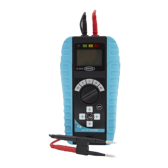
AutoTester
0-50 Volt, 80 Amp
RMM500
Multi-function Automotive Tester
Testeur automobile multifonction
Multifunktionelles Kfz-Testgerät
Tester diagnosi auto multifunzione
Medidor automovilístico multifunción
Multifunctionele diagnosetester
Multifunktionsbiltestare
Monitoimautotesteri
Wielofunkcyjny tester samochodowy
Multifunkční tester elektrického systému vozidel
Tester auto multifuncţional
Многофункциональный автомобильный тестер
INSTRUCTIONS
Retain these instructions for future reference
10422 RMM500 Instructions UK 140x170mm 15pp MULTI LANGUAGE.indb 1
Instructions
Mode d'emploi
Bedienungsanleitung
Istruzioni
www.ringautomotive.com
Instrucciones
Instrukcje
Instructies
Pokyny
Instruktioner
Instrucţiuni
Ohjeet
Инструкции
23/08/2017 17:13
Table des Matières

Sommaire des Matières pour ring RMM500
- Page 1 Multifunkční tester elektrického systému vozidel Tester auto multifuncţional Многофункциональный автомобильный тестер INSTRUCTIONS Instructions Instrucciones Instrukcje Mode d’emploi Instructies Pokyny Retain these instructions for future reference Bedienungsanleitung Instruktioner Instrucţiuni Istruzioni Ohjeet Инструкции www.ringautomotive.com 10422 RMM500 Instructions UK 140x170mm 15pp MULTI LANGUAGE.indb 1 23/08/2017 17:13...
- Page 2 When this mode is selected, you can test the continuity of the cable, circuit or common ground. The beeper will sound when the continuity is good. Diode & LED Test Whilst in the Continuity test mode, the condition of diodes and LEDs can also be tested. 10422 RMM500 Instructions UK 140x170mm 15pp MULTI LANGUAGE.indb 2 23/08/2017 17:13...
- Page 3 7 - POWER & ENTER button 8 - BACK button 9 - Direction buttons 10 - LCD display 11 - Status indicator 12 - Negative(-) connection 13 - Positive(+) connection 10422 RMM500 Instructions UK 140x170mm 15pp MULTI LANGUAGE.indb 3 23/08/2017 17:13...
-
Page 15: Présentation
Test de diode et de LED L'état des diodes et des LED peut également être testé tout en étant en mode Continuité. 10422 RMM500 Instructions UK 140x170mm 15pp MULTI LANGUAGE.indb 15 23/08/2017 17:13... - Page 16 9 - Touches directionnelles 10 - Écran LCD 11 - Indicateur d'état 12 - Branchement du fil de test négatif (-) 13 - Branchement du fil de test positif (+) 10422 RMM500 Instructions UK 140x170mm 15pp MULTI LANGUAGE.indb 16 23/08/2017 17:13...
-
Page 17: Configuration
3. À l'aide des touches , sélectionner le type de fusible à tester puis appuyer sur la touche 4. Sélectionner le calibre du fusible à l'aide des touches puis appuyer sur la touche 10422 RMM500 Instructions UK 140x170mm 15pp MULTI LANGUAGE.indb 17 23/08/2017 17:13... - Page 18 13. Si l'intensité mesurée dépasse la limite de calibre du fusible, Over Limit (dépassement de limite) s'affiche alors. Si cela se produit, vérifier que le bon calibre de fusible est sélectionné 10422 RMM500 Instructions UK 140x170mm 15pp MULTI LANGUAGE.indb 18 23/08/2017 17:13...
-
Page 19: Mesure De Courant En Série
Cette plage est utile pour contrôler les circuits d'une intensité plus élevée tels que ceux des moteurs d'essuie-glace, des ventilateurs de radiateur, des vitres électriques, etc. L'appel de courant s'affiche tel qu'indiqué ci-dessous 10422 RMM500 Instructions UK 140x170mm 15pp MULTI LANGUAGE.indb 19 23/08/2017 17:13... -
Page 20: Mesure De Tension
Tension de charge de l'alternateur 24 V intelligent Ignorer (normale) 35,1 V - 37,5 V Tension de charge de l'alternateur 24 V intelligent Contrôler l'alternateur/paramétrage (élevée) >37,6 V Affichage normal 10422 RMM500 Instructions UK 140x170mm 15pp MULTI LANGUAGE.indb 20 23/08/2017 17:13... -
Page 21: Test De Démarreur (Véhicules En 12 V/24 V)
19,0 V - 24,6 V Tension 24 V en phase de lancement (satisfaisante) 9. Pour quitter ce menu et revenir au menu principal, appuyer sur la touche 10422 RMM500 Instructions UK 140x170mm 15pp MULTI LANGUAGE.indb 21 23/08/2017 17:13... -
Page 22: Test D'alternateur (Alternateurs 12 V/24 V Classiques Et Intelligents)
10 s à 0 s 4. Lorsque le temporisateur régressif arrive à zéro, les résultats s'affichent automatiquement 5. Après 3 secondes, l'affichage passe automatiquement au test suivant : 10422 RMM500 Instructions UK 140x170mm 15pp MULTI LANGUAGE.indb 22 23/08/2017 17:13... -
Page 23: Test De Tension Avec Consommateurs
5. Attendre jusqu'à ce que le temporisateur régressif arrive à zéro Temporisation régressive de 10 s à 0 s 6. Lorsque le temporisateur régressif arrive à zéro, les résultats s'affichent automatiquement 10422 RMM500 Instructions UK 140x170mm 15pp MULTI LANGUAGE.indb 23 23/08/2017 17:13... -
Page 24: Mesure De Résistance
En mode Fréquence, il est possible de mesurer la vitesse et la forme des impulsions dans un circuit pour faciliter le diagnostic des problèmes, notamment les dysfonctionnements de capteurs. 10422 RMM500 Instructions UK 140x170mm 15pp MULTI LANGUAGE.indb 24 23/08/2017 17:13... -
Page 25: Mode Comptage D'impulsions
1. Positionner le sélecteur rotatif sur Continuité (position 2. Mettre les sondes en contact avec chaque extrémité du circuit à mesurer 3. Un signal sonore retentit si une continuité est détectée 10422 RMM500 Instructions UK 140x170mm 15pp MULTI LANGUAGE.indb 25 23/08/2017 17:13... -
Page 26: Test De Led
1. Mettre la sonde noire en contact avec le pôle négatif (-) de la LED et la sonde rouge en contact avec le pôle positif (+) de la LED – Si la LED s'allume, son état est satisfaisant 10422 RMM500 Instructions UK 140x170mm 15pp MULTI LANGUAGE.indb 26 23/08/2017 17:13... -
Page 27: Caractéristiques
0 - 50°C Type de piles : 3 x AA (non comprises) Avertissement de décharge des piles : < 3,8 V Mise hors tension automatique : après 10 minutes 10422 RMM500 Instructions UK 140x170mm 15pp MULTI LANGUAGE.indb 27 23/08/2017 17:13... - Page 158 Ring Automotive Limited, Gelderd Road, Leeds LS12 6NA England +44 (0)113 213 2000 +44 (0)113 231 0266 autosales@ringautomotive.com Website: www.ringautomotive.com L495 10422 RMM500 Instructions UK 140x170mm 15pp MULTI LANGUAGE.indb 158 23/08/2017 17:15...