Table des Matières
Publicité
Les langues disponibles
Les langues disponibles
Liens rapides
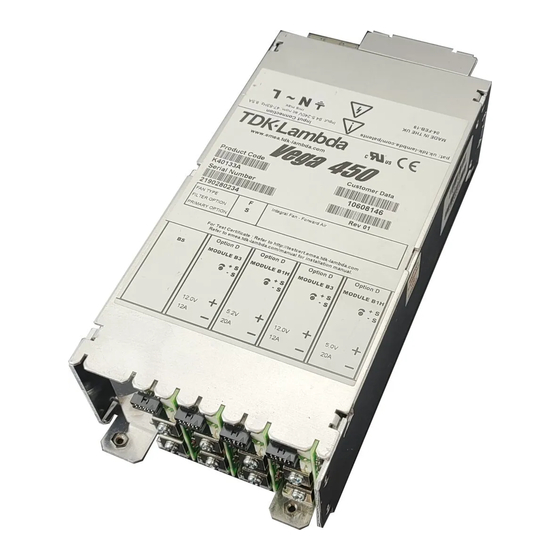
Vega 450 Handbook
ENGLISH
General Safety Instructions:
READ SAFETY INSTRUCTIONS
Servicing:
These products are not customer serviceable. TDK-Lambda UK LTD. and their authorised agents only are permitted
to carry out repairs.
Critical Components:
These products are not authorised for use as critical components in nuclear control systems, life support systems or
equipment for use in hazardous environments without the express written approval of the Managing Director of TDK-
Lambda EMEA.
Product Usage:
These products are designed for use within a host equipment which restricts access to authorised competent
personnel.
This product is a component power supply and is only to be installed by qualified persons within other equipment and
must not be operated as a stand alone product.
This product is for sale to business to business customers and can be obtained via distribution channels.
It is not intended for sale to end users.
This product is a component power supply and does not fall within the scope of the EMC directive. Compliance with
the EMC directive must be considered in the final installation. Please contact your local TDK-Lambda office.
Environmental:
These products are IPX0, and therefore chemicals/solvents, cleaning agents and other liquids must not be used.
Environment:
This power supply is a switch mode power supply for use in applications within a Pollution Degree 2, overvoltage
category II environment. Material Group IIIb PCB's are used within it.
Output Loading:
The output power taken from the power supply must not exceed the rating stated on the power supply label, except
as stated in the product limitations in this handbook.
Input Parameters:
This product must be operated within the input parameters stated in the product limitations in this handbook.
End of Life Disposal:
The unit contains components that require special disposal. Make sure that the unit is properly disposed of at the
end of its service life and in accordance with local regulations.
This product is a component power supply and is only to be installed by qualified persons within other equipment and
must not be operated as a stand alone product.
This product is for sale to business to business customers and can be obtained via distribution channels.
It is not intended for sale to end users.
This product is a component power supply and does not fall within the scope of the EMC directive. Compliance with
the EMC directive must be considered in the final installation. Please contact your local TDK-Lambda office
RISK OF ELECTRIC SHOCK
High Voltage Warning:
Dangerous voltages are present within the power supply. The professional installer must protect service personnel
from inadvertent contact with these dangerous voltages in the end equipment.
Page 1 of 35
17138 issue 35, Sept 2019
Publicité
Table des Matières

Manuels Connexes pour TDK-Lambda Vega 450


Sommaire des Matières pour TDK-Lambda Vega 450
- Page 1 General Safety Instructions: READ SAFETY INSTRUCTIONS Servicing: These products are not customer serviceable. TDK-Lambda UK LTD. and their authorised agents only are permitted to carry out repairs. Critical Components: These products are not authorised for use as critical components in nuclear control systems, life support systems or equipment for use in hazardous environments without the express written approval of the Managing Director of TDK- Lambda EMEA.
-
Page 2: Hot Surface
An internal fuse protects the unit and must not be replaced by the user. In case of internal defect, the unit must be returned to TDK-Lambda UK LTD or one of their authorised agents. The mains switch, where fitted, must not be used as the main disconnect device. - Page 3 Allgemeine Sicherheitsvorschriften: LESEN SIE DIE SICHERHEITSVORSCHRIFTEN Wartung: Diese Produkte können nicht durch den Kunden gewartet werden. Nur TDK-Lambda UK LTD. und deren zugelassene Vertriebshändler sind zur Durchführung von Reparaturen berechtigt. Kritische Komponenten: Diese Produkte sind nicht für die Verwendung als kritische Komponenten in nuklearen Kontrollsystemen, Lebenserhaltungssystemen oder Geräten in gefährlichen Umgebungen geeignet, sofern dies nicht ausdrücklich und...
-
Page 4: Gefahr Durch Elektrischen Schlag
Produkt auf Erdschluss geprüft werden. Eine interne Sicherung schützt das Gerät und darf durch den Benutzer nicht ausgetauscht werden. Im Fall von internen Defekten muss das Gerät an TDK-Lambda UK LTD oder einen der autorisierten Vertriebshändler zurückgeschickt werden. Der Schalter, sofern vorhanden, ist ein unipolares Gerät, das nicht als Hauptschalter zum Trennen des Gerätes verwendet werden darf. -
Page 5: Entretien
Consignes générales de sécurité: LIRE LES CONSIGNES DE SECURITE Entretien: Ces produits ne peuvent pas être réparés par l’utilisateur. Seuls, TDK-Lambda UK LTD et ses agents agréés sont autorisés à effectuer des réparations. Composants critiques: Ces produits ne doivent pas être utilisés en tant que composants critiques dans des systèmes de commande nucléaire, dans des systèmes de sauvetage ou dans des équipements utilisés dans des environnements dangereux,... -
Page 6: Surface Chaude
Un fusible interne protège le module et ne doit pas être remplacé par l'utilisateur. En cas de défaut interne, le module doit être renvoyé à TDK-Lambda UK LTD ou l'un de ses agents agréés. Le commutateur, s'il est installé, est un commutateur unipolaire et il ne doit pas être utilisé comme coupe-circuit principal. - Page 7 Manutenzione: Il cliente non può eseguire alcuna manutenzione su questi prodotti. L'esecuzione delle eventuali riparazioni è consentita solo a TDK-Lambda UK LTD e ai suoi agenti autorizzati. Componenti critici: Non si autorizza l'uso di questi prodotti come componenti critici all'interno di sistemi di controllo nucleari, sistemi necessari alla sopravvivenza o apparecchiature destinate all'impiego in ambienti pericolosi, senza l'esplicita approvazione scritta dell'Amministratore Delegato di TDK-Lambda EMEA.
- Page 8 Un fusibile interno protegge l'unità e non deve essere sostituito dall'utente. Nell'eventualità di un difetto interno, restituire l'unità a TDK-Lambda UK LTD o a uno dei suoi agenti autorizzati. L'interruttore, se fornito, è un dispositivo unipolare e non deve essere utilizzato come dispositivo principale di scollegamento.
- Page 9 Instrucciones generales de seguridad: LEA LAS INSTRUCCIONES DE SEGURIDAD Servicio: Estos productos no pueden ser reparados por los clientes. TDK-Lambda UK LTD. y sus agentes autorizados son los únicos que pueden llevar a cabo las reparaciones. Componentes fundamentales: Estos productos no pueden ser utilizados como componentes fundamentales en sistemas de control nuclear, sistemas de soporte vital o equipos a utilizar en entornos peligrosos sin el consentimiento expreso por escrito del Director General de TDK-Lambda EMEA.
- Page 10 Un fusible interno protege la unidad y este no debe ser nunca reemplazado por el usuario. En caso de existir algún defecto interno, la unidad debe ser enviada a TDK-Lambda UK LTD o a uno de sus agentes autorizados. El interruptor, de estar montado, es un dispositivo monopolar y no debe ser utilizado como dispositivo de desconexión principal.
- Page 11 Instruções gerais de segurança: LEIA AS INSTRUÇÕES DE SEGURANÇA Manutenção: Estes produtos não são podem ser submetidos a manutenção por parte do cliente. Apenas a TDK-Lambda UK LTD e os seus agentes autorizados têm permissão para realizar reparações. Componentes essenciais: Não é...
-
Page 12: Risco De Choque Eléctrico
Existe um fusível interno que protege a unidade e que não deve ser substituído pelo utilizador. Em caso de defeito interno, a unidade deve ser devolvida à TDK-Lambda UK LTD ou a um dos seus agentes autorizados. O interruptor, quando instalado, é um dispositivo de pólo simples, não devendo ser utilizado como o dispositivo de desactivação principal. -
Page 13: Environmental Specifications
These products are NOT suitable for use in the presence of flammable anaesthetic mixtures with air or with oxygen, or with nitrous oxide. • The Vega 450 range provides Reinforced insulation between input and outputs, and functional insulation between outputs and earth. •... - Page 14 Fast-ons Terminal block If the earth terminal of the Vega 450 PSU is connected to the main incoming earth conductor of the end equipment, the installer must cover the earth symbol with a label bearing the earth symbol of IEC60417-5019.
- Page 15 Vega 450 Handbook PRODUCTS COVERED Unit Configuration Code: V4 or Vega 450 range or Vega Smart (450W) or Vega Smart Plus (450W) where V4 = Vega 450 Range Vega Smart = Vega 450 PSU with primary digital option fitted Vega Smart Plus = Vega 450 PSU with primary and secondary digital options fitted.
- Page 16 Vega 450 Handbook For W2, W5 & W8 modules only: @ is followed by F, T, E or S where F = Fixed OVP T = Tracking OVP E = Fixed OVP, high current output S = Tracking OVP, high current output Followed by F or S, where F indicates fast-on output terminals and S indicates screw output terminals.
- Page 17 Vega 450 Handbook ELECTRICAL & THERMAL RATINGS: Input Parameters Standard 60601-1 60950-1 & 61010-1 Nominal input voltage 100-240Vac 100-240Vac Input voltage range 90-264Vac 90-264Vac Input frequency range 47 - 63Hz 47 - 63Hz Maximum Input Current 8.5A rms 8.5A rms Inrush Current <40A AT 25°C...
- Page 18 Vega 450 Handbook H2/1L 5.6-9/1.8-3.8V 10A/8A 90W/31W 20/8 15A/12A H2/1H 5.6-9/3.9-5.5V 10A/8A 90W/44W 20/8 15A/12A H2/2 5.6-9/5.6-9V 10A/6A 90W/54W 20/12 15A/9A H2/3 5.6-9/9.1-16.2V 10A/6A 90W/98W 20/18 15A/7.5A H2/4 5.6-9/16.3-25V 10A/4.5A 90W/113W 20/18 15A/6A H3/1L 9.1-16.2/1.8-3.8V 10A/8A 162W/31W 30/8 15A/12A >16V/N/A H3/1H 9.1-16.2/3.9-5.5V...
- Page 19 Vega 450 Handbook W2 & W5 is followed by V or R indicating voltage or resistance programming, followed by 1, 2, 3 or 4, where: 1 = Inhibit + Fixed or prog current limit + Fixed 0/V 2 = Inhibit + Fixed or prog current limit + Track 0/V...
- Page 20 Vega 450 Handbook Cooling Options: All PSUs: Input voltage: 100-240 V ac nom., 90-264V ac max., 47-63 Hz, 8.5A rms max. Module Dual Width Max AT Current Cooling Option Ambient Modules Power (W) (total) Rating (All (°C) Fitted Modules) F & D...
- Page 21 See diagrams at end of this section for locations of components in the PSU. Custom Models: All ratings as per standard models unless otherwise stated. Model: Vega 450 AFT B/S 24D5S 21D5S (NS-CLE-010) Input: 85-264Vac, 47-63Hz Maximum outputs: 24V, 12.5A; 21V, 7.143A Orientation: All except upside down and vertical with the airflow downwards Cooling: Papst 612NML or 612NGML fan fitted with up to 64 ohms total resistance in series.
- Page 22 M5 – 2.4 – 2.6Nm Adjustment and Derating: The Vega 450 series is designed to provide a max power of 450W at nominal output voltages. The following procedure must be used to ensure the PSU is operated within its ratings: •...
- Page 23 Vega 450 Handbook Mechanical Outline Drawings: Primary Options Specified Option Pin 5 Logic 0 Pin 6 Logic 1 Inhibit Outputs OFF Outputs OFF Enable Outputs ON Outputs ON Logic 0 = 0-0.8V Logic 1 = 2-5V with respect to 0V (Pin 3)
- Page 24 Vega 450 Handbook Module Good TWIN Output Module “N” Option TWIN Output Module “R” Option Page 24 of 35 17138 issue 35, Sept 2019...
- Page 25 Vega 450 Handbook Single Output Module Digital Option Single Output Wide Range Programmable Option Page 25 of 35 17138 issue 35, Sept 2019...
- Page 26 Vega 450 Handbook LAYOUT FOR VEGA 450 CONVERTER Page 26 of 35 17138 issue 35, Sept 2019...
- Page 27 Vega 450 Handbook LAYOUT OF VEGA TWIN MODULE LAYOUT OF VEGA H5/4 MODULE Page 27 of 35 17138 issue 35, Sept 2019...
- Page 28 Vega 450 Handbook LAYOUT OF VEGA SINGLE MODULE LAYOUT OF VEGA DUAL WIDTH MODULE Page 28 of 35 17138 issue 35, Sept 2019...
- Page 29 Vega 450 Handbook LAYOUT OF VEGA SINGLE MODULE HIGH CURRENT LAYOUT OF VEGA W5 MODULE Page 29 of 35 17138 issue 35, Sept 2019...
- Page 30 Vega 450 Handbook LAYOUT OF VEGA W8 MODULE LAYOUT OF VEGA W9 MODULE Page 30 of 35 17138 issue 35, Sept 2019...
- Page 31 Vega 450 Handbook LAYOUT OF VEGA OR-ING MODULE LAYOUT OF VEGA 100mA PRIMARY OPTION Page 31 of 35 17138 issue 35, Sept 2019...
- Page 32 Vega 450 Handbook LAYOUT OF VEGA 300mA PRIMARY OPTION LAYOUT OF VEGA 1A PRIMARY OPTION Page 32 of 35 17138 issue 35, Sept 2019...
- Page 33 Vega 450 Handbook LAYOUT OF VEGA PRIMARY MICRO OPTION Customer Fixings Customer Air and Fixing Detail Page 33 of 35 17138 issue 35, Sept 2019...
- Page 34 Vega 450 Handbook IEC 60320 (Switched) Input Quick Connect (Faston) Input Page 34 of 35 17138 issue 35, Sept 2019...
- Page 35 Vega 450 Handbook Right Angle Screw Terminal Input Module Positions TDK-Lambda UK Ltd Kingsley Avenue, Ilfracombe Devon, EX34 8ES Telephone - Sales and Service +44 (0)1271 856666 Head Office and Works +44 (0)1271 856600 Facsimile +44 (0)1271 864894 WEBSITE: www.uk.tdk-lambda.com...