Table des Matières
Publicité
Les langues disponibles
Les langues disponibles
Liens rapides
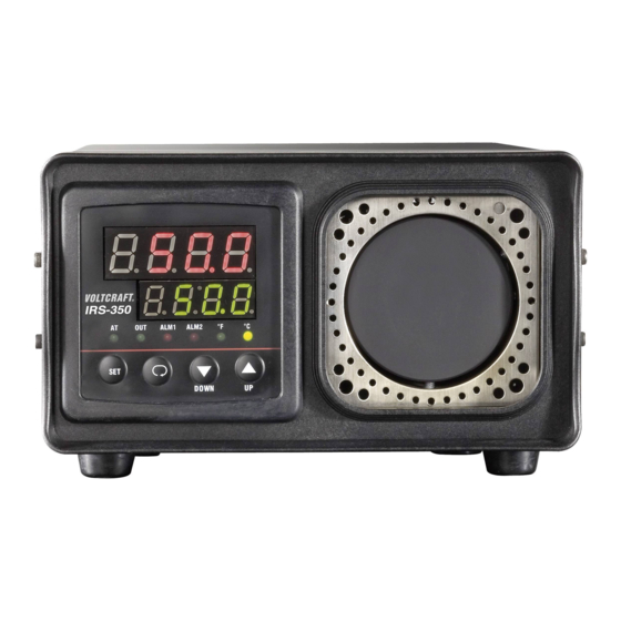
IRS-350 Schwarzstrahler
B E DI EN UNG SANLEI TUNG
IRS-350 Blackbody
OPERATING INSTRUCTIONS
Radiateur de Planck IRS-350
NOTICE D'EMPLOI
IRS-350 zwartstraler
GEBRUIKSAANWIJ ZI NG
Best.-Nr. / Item-No. /
N° de commande / Bestnr.:
10 13 66
VOLTCRAFT
®
Seite 4 - 12
Page 13 - 21
Page 22 - 30
Pagina 31 - 39
°
Version 11/08
Publicité
Chapitres
Table des Matières
Dépannage

Sommaire des Matières pour VOLTCRAFT IRS-350
- Page 1 IRS-350 Schwarzstrahler B E DI EN UNG SANLEI TUNG Seite 4 - 12 IRS-350 Blackbody OPERATING INSTRUCTIONS Page 13 - 21 Radiateur de Planck IRS-350 NOTICE D’EMPLOI Page 22 - 30 IRS-350 zwartstraler GEBRUIKSAANWIJ ZI NG Pagina 31 - 39 Best.-Nr.
- Page 2 These operating instructions represent the technical status at the time of printing. Changes in technology and equipment reserved. © Copyright 2008 by Voltcraft ® Informations /légales dans nos modes d'emploi Ce mode d'emploi est une publication de la société Voltcraft ® , Lindenweg 15, D-92242 Hirschau/Allemagne, Tél. +49 180/586 582 7 (www.voltcraft.de).
- Page 3 Diese Bedienungsanleitung gehört zu diesem Produkt. Sie enthält wichtige Hinweise zur Inbetriebnahme und Handhabung. Achten Sie hierauf, auch wenn Sie dieses Produkt an Dritte weitergeben. Heben Sie deshalb diese Bedienungsanleitung zum Nachlesen auf! Eine Auflistung der Inhalte finden Sie in dem Inhaltsverzeichnis mit Angabe der entsprechenden Seitenzahlen auf Seite 4.
-
Page 5: Table Des Matières
Mit Voltcraft® werden Sie als anspruchsvoller Bastler ebenso wie als professioneller Anwender auch schwierigen Aufgaben gerecht. Voltcraft® bietet Ihnen zuverlässige Technologie zu einem außerge- wöhnlich günstigen Preis-/Leistungsverhältnis. Wir sind uns sicher: Ihr Start mit Voltcraft ist zugleich der Beginn einer langen und guten Zusammen- arbeit. Viel Spaß mit Ihrem neuen Voltcraft®-Produkt! Inhaltsverzeichnis Einführung ..............................4... -
Page 6: Sicherheitshinweise
Die Temperatureinstellung in °Celsius erfolgt bedienungsfreundlich über Folientasten und kann über Soll- und Ist-Temperaturanzeigen kontrolliert werden. Ein eingebauter Lüfter ermöglicht zügige Tempe- raturänderungen an der Kalibrierfläche. Der Einstellbereich reicht von +50 bis +350 °C. Zusätzlich ist eine Öffnung zum Abgleich oder Test von Kontaktthermometern mit Tauch- oder Einstich- fühlern (max. - Page 7 Das „Hand“-Symbol ist zu finden, wenn Ihnen besondere Tipps und Hinweise zur Bedie- nung gegeben werden sollen. Anschlusspunkt für den inneren Schutzleiter; Diese Schraube/dieser Kontakt darf nicht gelöst werden. Nur zur Verwendung in trockenen Innenbereichen Achtung heiße Oberfläche! Es besteht Verbrennungsgefahr beim Berühren. Berühren Sie die Heiz- und Kühlflächen niemals während des Betriebes.
-
Page 8: Lieferumfang
• nach längerer Lagerung unter ungünstigen Verhältnissen oder • nach schweren Transportbeanspruchungen. Beachten Sie auch die Sicherheitshinweise in den einzelnen Kapiteln bzw. in den Bedienungsanleitun- gen der zu kalibrierenden Geräte. Lieferumfang IRS-350 Schwarzstrahler Netzkabel Bedienungsanleitung Bedienelemente (Bild auf Ausklappseite) Funktionsanzeigen Anzeige nur für Werksabgleich... -
Page 9: Inbetriebnahme
Inbetriebnahme Aufstellen des Gerätes Stellen Sie das Gerät auf einer ebenen, wärmebeständigen Oberfläche ab. Die Ablageflä- che kann sich durch den austretenden Luftstrom leicht erwärmen. Halten Sie brennbare Gegenstände von der Kalibrierfläche (5) fern. Achten Sie auf ausreichende Luftzirkulation. Ein Abstand von mind. 20 cm muss allseitig eingehalten werden. Gerät anschließen und einschalten Stecken Sie das beiliegende Netzkabel in den rückseitigen Netzanschluss (14) und in eine Netzsteck- dose mit Schutzerdung. -
Page 10: Messbetrieb
Erfolgt eine Temperaturerhöhung, wird der Heizvorgang durch die Funktionsanzeige „OUT“ (1) signalisiert. Erfolgt eine Temperatursenkung, erlischt bzw. blinkt die Funktionsanzeige „OUT“. Liegt der Ist-Tempera- turwert (Anzeige 3) um >4 °C über dem Soll-Temperaturwert (Anzeige 2), werden die beiden roten Funk- tionsanzeigen „ALM1“... -
Page 11: Wartung Und Reinigung
An der Gehäuseoberseite befindet sich eine Öffnung (4) für Einstich-Thermofühler mit einem Schaftdurchmesser von max. 3 mm. Diese Öffnung dient dazu, normale Thermome- ter abzugleichen oder die Temperatur an der Kalibrierfläche mit einem Kontakt-Thermome- ter zu überwachen. Stecken Sie dazu den Fühler senkrecht in die Öffnung, bis der Fühler Kontakt hat. Nach Messende muss die Temperatur auf <60 °C geregelt werden. -
Page 12: Behebung Von Störungen
Andere Reparaturen als zuvor beschrieben sind ausschließlich durch einen autorisierten Fachmann durchzuführen. Sollten Sie Fragen zum Umgang des Messgerätes haben, steht Ihnen unser techn. Support unter folgender Telefonnummer zur Verfügung: Voltcraft, Lindenweg 15, 92242 Hirschau, Tel.-Nr. 0180 / 586 582 7... -
Page 13: Technische Daten
Technische Daten Betriebsspannung..........230 V/AC +/- 10% Leistungsaufnahme max.........210 W Temperaturbereich ..........50 bis 350 °C Genauigkeit............+/- 0,5 °C bei 100 °C +/- 1,2 °C bei 350 °C Stabilität ............+/- 0,1 °C bei 100 °C +/- 0,2 °C bei 350 °C Anzeigenauflösung ..........0,1 °C Emissionsgrad der Messfläche......0,95 Messfläche Ø... -
Page 14: Intended Use
With Voltcraft®, you will be able to cope even with difficult tasks as an ambitious hobbyist or as a pro- fessional user. Voltcraft® offers reliable technology with an exceptional cost-performance ratio. -
Page 15: Safety Instructions
The temperature in °Celsius is set by membrane buttons and can be controlled through displays of actu- al temperature and setpoint temperature. The integrated fan allows quick temperature changes of the calibration area. The setting range is from +50 to +350 °C. In addition, the device is equipped with an opening at the housing top to calibrate or test contact ther- mometers with immersion sensors or penetration probes (max. - Page 16 The hand symbol indicates special information and advice on the operation of the device. Terminal for the internal protective earth conductor; this screw/contact must not be unscrewed. Only for dry indoor use Caution, hot surface! There is a risk of burns when touched. Never touch heating or cooling areas during opera- tion.
-
Page 17: Scope Of Delivery
• after it has been exposed to heavy stress during transport. You should also observe the safety instructions in the individual chapters of these operating instructions and in the operating instructions of the devices to be calibrated. Scope of delivery IRS-350 Blackbody Mains cable Operating instructions Controls... -
Page 18: Operation
Operation Positioning the device Place the device on the flat and heat-resistant surface. The surface might get warm due to the air flow coming from the device. Keep inflammable objects away from the calibration area (5). Ensure proper ventilation. Keep a minimum of 20 cm on all sides. Connecting an switching on the device Connect the mains cable to the power supply socket at the back (14) and to a mains socket with protec- tive grounding. -
Page 19: Measuring
If the temperature is increased, the heating process is indicated by function display OUT (1). If the temperature is decreased, function display OUT goes out or starts flashing. If the actual tempera- ture (display 3) is above the setpoint temperature by more than 4°C (display 2), both red function dis- plays ALM1 and ALM2 are activated. -
Page 20: Maintenance And Cleaning
At the housing top, there is an opening (4) for penetration probes with a shaft diameter of max. 3 mm. This opening is used to calibrate normal thermometers and to control the tem- perature of the calibration area with a contact thermometer. Insert the probe at right angle into the opening until the probe has made contact. -
Page 21: Troubleshooting
Repairs other than those described should only be carried out by an authorised specialist. If you have questions concerning the use of the measuring device, our technical support service is available at the following telephone number: Voltcraft, Lindenweg 15, 92242 Hirschau, tel. no. 0180 / 586 582 7... -
Page 22: Specifications
Specifications Operating voltage ..........230 V/AC +/- 10% Power consumption max.........210 W Temperature range ..........50 to 350 °C Accuracy............+/- 0.5 °C at 100 °C +/- 1.2 °C at 350 °C Stability ............+/- 0.1 °C at 100 °C +/- 0.2 °C at 350 °C Display step size..........0.1 °C Emission ratio of measuring area ....0,95 Emission area Ø... - Page 23 Introduction Chère cliente, cher client, Vous avez pris une très bonne décision en achetant ce produit Voltcraft ® et nous vous en remercions. Vous avez acquis un produit de qualité issu d’une marque se distinguant par sa compétence technique, son extraordinaire performance et une innovation permanente dans le domaine de la métrologie et de la technique de charge et de réseau.
-
Page 24: Consignes De Sécurité
La température en °Celsius se règle aisément via les touches à membrane et peut être contrôlée par le biais des indicateurs de température de consignes et réelles. Un ventilateur incorporé permet de modi- fier rapidement la température sur la surface d´étalonnage. La plage de réglage est comprise entre +50 et +350 °C. - Page 25 Le symbole de la « main » précède les recommandations et indications d’utilisation particulières. Point de connexion pour le conducteur de protection interne ; il est interdit de dévisser cette vis. N’utiliser qu’à l’ intérieur dans des locaux secs Attention: surface très chaude! Risque de brûlures en cas de contact.
-
Page 26: Contenu De La Livraison
Tenez également compte des consignes de sécurité supplémentaires de chaque chapitre de ce mode d’emploi ainsi que des modes d’emploi des appareils devant être étalonnés. Contenu de la livraison Radiateur de Planck IRS-350 Câble secteur Notice d’utilisation Éléments de commande... -
Page 27: Mise En Service
Mise en service Installation de l’appareil Installez l’appareil sur une surface plane et résistante à la chaleur. La surface de dépôt peut chauffer légèrement au contact du flux d’air qui s´échappe. Conservez les objets inflammables à l´écart de la surface d´étalonnage (5). Veillez à une circulation suffisante de l´air. -
Page 28: Mode De Mesure
Si la température est augmentée, la phase chauffante est signalée par l´affichage des fonctions “OUT“ (1) . Une diminution de la température entraîne l´extinction ou le clignotement de l´affichage “OUT”. Si la tem- pérature réelle (affichage 3) est supérieure de >4 °C à la température de consigne (affichage 2), les deux affichages rouges “ALM1“... -
Page 29: Maintenance Et Nettoyage
Une ouverture (4) destinée à la thermo-sonde à pointe d’un diamètre de corps de maximum 3 mm est logée sur le dessus du boîtier. Cette ouverture permet d’ajuster les thermomètres normaux ou de surveiller la température de la surface d´étalonnage à l´aide d´un thermo- mètre à... -
Page 30: Dépannage
Si vous deviez avoir des questions concernant la manipulation de l’appareil de mesure, notre support technique est à votre disposition par téléphone au numéro suivant : Voltcraft, D-92242 Hirschau, Lindenweg 15, tél. : +49 (0) 180/586 582 7... -
Page 31: Caractéristiques Techniques
Caractéristiques techniques Tension de service ..........230 V/AC +/- 10% Puissance absorbée maxi........210 W Plage de température ........50 à 350 °C Précision............+/- 0,5 °C pour 100 °C +/- 1,2 °C pour 350 °C Stabilité............+/- 0,1 °C pour 100 °C +/- 0,2 °C pour 350 °C Résolution de l’affichage........0,1 °C Emissivité... -
Page 32: Voorgeschreven Gebruik
Voltcraft® biedt u betrouwbare technologie tegen een buitengewoon voor- delige prijs-kwaliteitverhouding. Wij zijn ervan overtuigd: uw keuze voor Voltcraft is tegelijkertijd het begin van een langdurige en pret- tige samenwerking. Veel plezier met uw nieuwe Voltcraft®-product! -
Page 33: Veiligheidsvoorschriften
De temperatuurinstelling in °Celcius vindt gebruiksvriendelijk plaats via folietoetsen en kan via de dis- plays voor gewenste en werkelijke waarde worden gecontroleerd. Een ingebouwde ventilator maakt vlot- te temperatuurveranderingen op het kalibratievlak mogelijk. Het instelbereik reikt van +50 tot +350 °C. Daarnaast is een opening bovenin de behuizing aanwezig voor het afstellen of testen van contactther- mometers met dompel- of insteekvoelers (max. - Page 34 Het “hand”-symbool vindt u bij bijzondere tips of instructies voor de bediening. Aansluitpunt voor de interne aardleiding; deze schroef/dit contact mag niet losgemaakt worden. Alleen voor toepassingen in droge ruimtes binnenshuis Pas op: oppervlak wordt erg heet! Er bestaat verbrandingsgevaar bij aanraking. Raak de verwarmings- en koeloppervlakken niet aan tijdens het gebruik.
-
Page 35: Omvang Van De Levering
• het apparaat tijdens transport zwaar is belast. Neem ook de veiligheidsvoorschriften in de afzonderlijke hoofdstukken van deze handleiding en in de gebruiksaanwijzing van de te kalibreren apparaten in acht. Omvang van de levering IRS-350 zwartstraler Netsnoer Gebruiksaanwijzing Bedieningselementen (Zie afbeelding op de uitklappagina) -
Page 36: Opstellen Van Het Apparaat
Ingebruikneming Opstellen van het apparaat Zet het apparaat op een vlak, warmtebestendig oppervlak. Deze plaats kan door de uittre- dende luchtstroom warm worden. Houd brandbare voorwerpen uit de buurt van het kali- bratievlak (5). Zorg voor voldoende luchtcirculatie. Een afstand van minimaal 20 cm moet aan alle kanten worden aangehouden. -
Page 37: Meetfuncties
Als een temperatuurverhoging plaatsvindt, wordt het verwarmingsproces door de functieaanduiding „OUT“ (1) aangegeven. Als een temperatuurdaling plaatsvindt, gaat de functieaanduiding “OUT” uit of begint te knipperen. Als de werkelijke temperatuurwaarde (indicatie 3) met >4 °C boven de gewenste temperatuurwaarde (indi- catie 2) ligt, worden de beide rode functieaanduidingen „ALM1“... -
Page 38: Onderhoud En Reiniging
Bovenin de behuizing bevindt zich een opening (4) voor een thermische insteekvoeler met een schachtdiameter van max. 3 mm. Deze opening is bestemd voor het afstellen van een normale thermometer of voor het bewaken van de temperatuur op het kalibratievlak met een contactthermometer. -
Page 39: Verhelpen Van Storingen
Andere reparaties dan hierboven beschreven, mogen uitsluitend door een erkende vakman worden uitgevoerd. Bij vragen over het gebruik van het meetapparaat staat onze technische helpdesk onder het volgende telefoonnummer ter beschikking: Voltcraft, D-92242 Hirschau, Lindenweg 15, tel. +49 (0)180 / 586.582 7... -
Page 40: Technische Gegevens
Technische gegevens Voedingsspanning ..........230 V/AC +/- 10% Stroomverbruik max.........210 W Temperatuurbereik ..........50 tot 350 °C Nauwkeurigheid ..........+/- 0,5 °C bij 100 °C +/- 1,2 °C bij 350 °C Stabiliteit ............+/- 0,1 °C bij 100 °C +/- 0,2 °C bij 350 °C Weergaveresolutie ..........0,1 °C Emissiegraad van het meetvlak ......0,95 Meetvlak Ø...