Table des Matières

Publicité

Les langues disponibles

Les langues disponibles

Liens rapides

WEDECO Aquada
Installation and Maintenance Instructions
GB
Installations- und Wartungsanleitung
DE
Notice d'installation et de Maintenance
F
Istruzioni di Installazione e Manutenzione
I

Publicité

Table des Matières
loading

Sommaire des Matières pour ITT WEDECO Aquada 1

  • Page 1 WEDECO Aquada Installation and Maintenance Instructions Installations- und Wartungsanleitung Notice d’installation et de Maintenance Istruzioni di Installazione e Manutenzione...
  • Page 2: Table Des Matières

    Contents General & Applications Assembly & Installation 2.1. Reactor 2.1.1. Assembly of Reactor 2.1.2. Installation of Quartz Sleeve and of UV Lamp 2.1.2.1. Cleaning and Replacement of Quartz Sleeve 2.1.2.2. Fitting of UV Sensor (only for Maxima) 2.1.3. Connection to the Water Line Network 2.2. Control System 2.2.1.
  • Page 3: General & Applications

    UV reactor. ATTENTION: Correct function (disinfection performance) can only be guaran- teed when original ITT Water & Wastewater spare parts (lamps, ballasts, etc. ) are used. Should you have any questions please contact: www.wedeco.com Tel.: +49 (0) 5221 930-777...
  • Page 4: General Safety Instructions

    • Make sure this disinfection unit is only used for the intended purpose as describ- ed in the operating instructions. The use of additional apparatus, which have not been recommended by and are not sold by ITT Water & Wastewater can cause an unsafe situation.
  • Page 5 • Ensure the disinfection unit is electrically isolated before: A. Carrying out repairs REMARK: We recommend that any maintenance is carried out by qualified persons. B. Cleaning C. Replacement of the UV lamp • The unit is to be depressurized before maintenance • Do not use the UV lamp outside of the UV disinfection reactor WEDECO UV lamps have been designed for permanent operation to reach their best disinfection capacity.
  • Page 6: Assembly & Installation

    2. Assembly & Installation Make sure the national standards and prescriptions for assem- bly and installation are observed. Installation must be carried out only by qualified technicians. The following items must be checked prior to installation: • A max. operating pressure of 1000 K Pa (10 bar) must not be exceeded •...
  • Page 7: Assembly Of Reactor

    2.1.1. Assembly of Reactor • Before installation ensure you know which reactor type you are using. (Information about the reactor type can be found on the type plate) • Make sure that there is enough free space above the reactor (for dimensions see section 2.1.), otherwise it will not be possible to install the UV lamp and to maintain the system •...
  • Page 8: Installation Of Quartz Sleeve And Of Uv Lamp

    2.1.2. Installation of Quartz Sleeve and of UV Lamp The reactor is supplied together with a built-in quartz sleeve. The black head piece in which the UV lamp is to be inserted has been screwed to a tightness of 5 Nm in our factory.
  • Page 9 Assembling manual The UV lamp is also to be cleaned before assembly. It is to be inserted into the Transparent lamp head piece from above until connection the two transparent catching tabs of the connecting plug UV lamp lock into place in the head piece.
  • Page 10: Fitting Of Uv Sensor (Only For Maxima)

    2.1.2.2. Fitting of UV Sensor In our factory the UV sensor has been fitted to the control (only for Maxima model). It is only to be screwed to the reactor. Tightening should be carried out with a light tool only. A starting torque of 5 Nm is sufficient. Make sure this torque is not excee- ded, otherwise the quartz glass in the sensor may be damaged.
  • Page 11: Control System

    2.2. Control System The following equipment variants can be supplied: 1. Altima • Visual function control of UV lamp by transparent lamp connection • Control box which can be fastened easily (assembly on the wall or reactor) 2. Proxima • As Altima variant •...
  • Page 12: Assembly Of Control Box

    2.2.1. Assembly of the Control Box The control box can be fitted directly to the reactor by means of the supplied faste- ning bands. Pull bands through the opening of the housing and fasten them to the reactor. • Assembly on the wall is also possible. For this method drill two holes (hole spacing 134 mm) and fit dowels and screws.
  • Page 13: Connection Of Uv Lamp

    2.2.3. Connection of UV Lamp • Unpack UV lamp and wipe it with a clean cloth (do not touch the lamp with your fingers) • Insert the lamp into the head piece until the transparent catching tabs of the lamp connecting plug lock into place in the head piece (when you insert the lamp, slightly press in catching tabs with two fingers;...
  • Page 14: Units Without Solenoid Valve

    • Press Reset button for approx. 10 seconds after having switched on the unit, until you hear a signal • The unit is now in the warm up phase. After 5 minutes the solenoid valve is switched on and fully opened. •...
  • Page 15: Tightness Test

    3.2. Tightness Test After commissioning, all screw connections are to be checked for tightness. ITT Water & Wastewater do not assume any responsibility for water damage(s)! 4. Software The Aquada units (Proxima & Maxima) are equipped with a monitoring unit which is controlled by a micro-controller.
  • Page 16: Alarm Messages

    4.1. Alarm Messages The following alarm messages can occur during operation: AL 1 » UV lamp failed AL 2 » UV intensity less than 55 % of set value AL 3 » End of lamp life (days of use = 0) AL 4 » UV intensity between 55 % and 70 % of set value AL 5 »...
  • Page 17: New Start After Replacement Of Uv Lamp

    Alarm 4 • Normal UV lamp ageing (disinfection is still given) • Cleaning could be required soon • Lamp filament wiring is in front of the sensor window » Normal operating conditions can be restored by cleaning the unit » In the display „HI“ is replaced by „LO“ (only Maxima) »...
  • Page 18: Exploded Diagram

    5. Exploded Diagram 1 » control box 2 » reactor 3 » quartz sleeve 4 » UV lamp 5 » head piece 6 » O-ring (head piece) 7 » lamp connection 8 » O-ring (quartz sleeve) 9 » UV sensor 10 »...
  • Page 19: Spare Parts List

    6. Spare Parts List Spare Part No. Description 760054 Control Box AQUA 1 Altima 760055 Control Box AQUA 2 & 4 Altima 760056 Control Box AQUA 7 & 10 Altima 760057 Control Box AQUA 1 Proxima 760058 Control Box AQUA 2 & 4 Proxima 760059 Control Box AQUA 7 &...
  • Page 21 WEDECO Aquada Installation and Maintenance Instructions Installations- und Wartungsanleitung Notice d’installation et de Maintenance Istruzioni di Installazione e Manutenzione...
  • Page 22 Inhalt Allgemeines & Anwendungen Montage und Installation 2.1. Reaktor 2.1.1. Montage des Reaktors 2.1.2. Einbau des Quarzrohres und des UV-Strahlers 2.1.2.1. Säubern und Austauschen des Quarzrohres 2.1.2.2. Anbringen des UV-Sensors (nur Maxima) 2.1.3. Wasseranschlüsse herstellen 2.2. Steuerung 2.2.1. Montage der Steuerung 2.2.2. Elektrische Anschlüsse 2.2.3.
  • Page 23: Allgemeines & Anwendungen

    1. Allgemeines & Anwendungen Die Desinfektion mittels ultraviolettem Licht (UV) ist ein wirksames, wirtschaftliches und besonders umweltfreundliches Verfahren. UV-Licht tötet pathogene Mikroorganismen innerhalb von Sekunden ohne Rück- stände, schädliche Nebenprodukte oder Geruchs- und Geschmacksbeeinträchti- gungen. Eine Gefährdung des Betriebspersonals durch den Umgang mit gesund- heitsschädlichen Chemikalien ist dadurch ebenfalls ausgeschlossen.
  • Page 24: Allgemeine Sicherheitshinweise

    • Verwenden Sie dieses Desinfektionsgerät nur für den vorgesehenen Zweck wie in der Betriebsanleitung beschrieben. Die Verwendung von Zusatzgeräten, die nicht von ITT Water & Wastewater empfohlen oder vertrieben werden, können einen unsicheren Zustand hervorrufen. • Dieses Desinfektionsgerät ist vor Gebrauch ordnungsgemäß und in Übereinstimm- ung mit der Betriebsanleitung zu installieren.
  • Page 25 • Das UV-Desinfektionsgerät ist immer vom Stromkreis zu trennen bevor: A. Irgendwelche Reparaturen durchgeführt werden ANMERKUNG: Wir empfehlen dringend, dass jegliche Wartungsarbeiten durch qualifi- ziertes Fachpersonal ausgeführt wird. B. Eine Reinigung durchgeführt wird C. Der Austausch des UV-Strahlers vorgenommen wird • Vor Wartungsarbeiten das Gerät immer drucklos machen. • Den UV-Strahler nicht außerhalb des UV-Desinfektionsgerätes betreiben. Die WEDECO UV-Strahler sind für den Dauerbetrieb ausgelegt und erreichen dann ihre größte Desinfektionsleistung.
  • Page 26: Montage Und Installation

    2. Montage und Installation Bei der Montage und Installation sind die landesüblichen Nor- men und Vorschriften einzuhalten. Die Installation darf nur von Fachkräften durchgeführt werden. Vor der Installation sind folgende Punkte sicherzustellen: • Der max. Betriebsdruck von 1000 K Pa (10 bar) darf nicht überschritten werden •...
  • Page 27: Montage Des Reaktors

    • Bei Geräten mit UV-Sensor ist nur eine vertikale Montage des Reaktors zulässig. • Der Reaktor ist frostsicher zu montieren. • ITT Water & Wastewater empfiehlt den Reaktor mit einer Metallleitung anzu- schließen (Kupfer, Stahl) Kunststoffleitungen müssen aus UV beständigem...
  • Page 28: Einbau Des Quarzrohres Und Des Uv-Strahlers

    2.1.2. Einbau des Quarzrohres und des UV-Strahlers Der Reaktor wird mit eingebautem Quarzrohr geliefert. Das schwarze Kopfstück, in das der UV-Strahler eingeführt wird, ist mit 5 Nm werksseitig verschraubt worden. Einbau UV-Strahler siehe Punkt 2.2.3. 2.1.2.1. Säubern und Austauschen des Quarzrohres Der transparente Stecker des Strahleranschlusses ist durch leichtes drehen nach links oder rechts (bis auf die Erhöhung im Kopfstück) abzuziehen.
  • Page 29 Montageanleitung Der UV-Strahler ist ebenfalls vor dem Einbau mit einem trockenen Tuch zu säubern. Transparenter Strahleranschluss Er wird von oben durch das Kopfstück geführt, bis die beiden transparenten Rast- UV-Strahler fahnen des Anschlusssteck- ers im Kopfstück einrasten. Kopfstück Nach dem Einsetzen des UV- Strahlers ist der transparente Strahleranschlussstecker auf das Kopfstück aufzustecken...
  • Page 30: Anbringen Des Uv-Sensors (Nur Maxima)

    2.1.2.2. Anbringen des UV-Sensors Der UV-Sensor ist werksseitig an der Steuerung angebracht (nur Maxima). Er muss lediglich an den Reaktor geschraubt werden. Die Verschraubung darf nicht mit schwerem Werkzeug erfolgen. Der Sensor sollte handfest (ca. 5 Nm) angezogen werden. Bei Missachtung kann es zur Zerstörung der im Sensor befindlichen Quarz- glasscheibe kommen.
  • Page 31: Steuerung

    2.2. Steuerung Es sind folgende Ausstattungsvarianten erhältlich: 1. Altima • Optische Funktionskontrolle des UV-Strahlers durch transparenten Strahleran- schluss • leicht zu befestigende Steuerung (Wand oder Reaktormontage) 2. Proxima • Zusätzlich zum Umfang der Altima-Variante • Anschlussmöglichkeit eines Magnetventils, das einen Durchfluss nur bei einge- schaltetem UV Strahler zulässt •...
  • Page 32: Montage Der Steuerung

    2.2.1. Montage der Steuerung Die Steuerung kann mit den mitgelieferten Befestigungsbändern direkt am Reaktor befestigt werden. Befestigungsbänder durch die Ge häuse-Öffnung ziehen und fest am Reaktor befestigen. • Eine Wandmontage ist ebenfalls möglich. Hierbei sind zwei Löcher zu bohren (Lochabstand 134 mm) und mit Dübeln und Schrauben zu versehen. Dann lässt sich das Steuergehäuse mit den dafür vorgesehenen Löchern auf die Schrauben einhängen.
  • Page 33: Anschluss Des Uv-Strahlers

    2.2.3. Anschluss des UV Strahlers • Der UV-Srahler ist aus der Verpackung zu entfernen und mit einem sauberen Tuch abzuwischen (nicht mit den Fingern auf den Strahler fassen) • Den Strahler in das Kopfstück einführen bis die transparenten Rastfahnen des Strahlersteckers im Kopfstück einrasten.
  • Page 34: Geräte Ohne Magnetventil

    • Den Reset Button nach dem Einschalten ca. 10 sek. gedrückt halten bis ein Signal- ton zu hören ist • Das Gerät befindet sich nun in der Aufwärmphase. Nach 5 Minuten wird das Magnetventil eingeschaltet und hat nun vollen Durchfluss. •...
  • Page 35: Dichtigkeitsprüfung

    3.2. Dichtigkeitsprüfung Nach der Inbetriebnahme sind alle Schraubverbindungen auf Dichtigkeit zu überprüfen. ITT Water & Wastewater übernimmt keine Haftung für Wasser- schäden! 4. Software Die Aquada-Geräte (Proxima & Maxima) verfügen über eine Mikrokontroler gesteu- erte Überwachungseinheit. Das Aquada-Gerät (Altima) verfügt über eine optische Funktionskontrolle (Punkt 3.1.1.)
  • Page 36: Fehlermeldungen

    4.1. Fehlermeldungen Folgende Fehlermeldungen können während des Betriebes auftreten: AL 1 » UV-Strahler ausgefallen AL 2 » UV-Intensität unter 55 % des Sollwertes AL 3 » Ende der Strahler Lebensdauer (Nutzungstage = 0) AL 4 » UV-Intensität zwischen 55 % und 70 % des Sollwertes (Display Anzeige „LO“) AL 5 » UV-Strahler Lebensdauer < 30 Nutzungstage Alarm 1 •...
  • Page 37: Neustart Nach Tausch Des Uv Strahlers

    Alarm 4 • Normale UV-Strahler Alterung (Entkeimung ist noch gegeben) • Eine Reinigung kann bald erforderlich sein • Strahlerrückführung verläuft vor dem Sensorfenster » Durch die Reinigung des Gerätes wird der Normale Betriebszustand wieder er- reicht » Die Displayanzeige „HI“ wird durch „LO“ ersetzt (nur Maxima) »...
  • Page 38: Explosionszeichnung

    5. Explosionszeichnung 1 » Steuerung 2 » Reaktor 3 » Quarzrohr 4 » UV-Strahler 5 » Kopfstück 6 » O-Ring (Kopfstück) 7 » Strahleranschluss 8 » O-Ring (Quarzrohr) 9 » UV-Sensor (Maxima) 10 » Sensor Befestigung 11 » Befestigung Steuerung 12 »...
  • Page 39: Ersatzteilliste

    6. Ersatzteilliste Ersatzteil-Nr. Ersatzteil-Bezeichnung 760054 Baugr. Schaltkasten AQUA 1 Altima 760055 Baugr. Schaltkasten AQUA 2 & 4 Altima 760056 Baugr. Schaltkasten AQUA 7 & 10 Altima 760057 Baugr. Schaltkasten AQUA 1 Proxima 760058 Baugr. Schaltkasten AQUA 2 & 4 Proxima 760059 Baugr.
  • Page 41 WEDECO Aquada Installation and Maintenance Instructions Installations- und Wartungsanleitung Notice d’installation et de Maintenance Istruzioni di Installazione e Manutenzione...
  • Page 42 Sommaire Généralités et applications Montage et installation 2.1. Réacteur 2.1.1. Montage du Réacteur 2.1.2. Installation de la gaine de quartz et de la lampe UV 2.1.2.1. Nettoyage et remplacement de la gaine de quartz 2.1.2.2. Mise en place du capteur UV 2.1.3. Raccordement au circuit d’eau 2.2. Système de commande 2.2.1.
  • Page 43: Généralités Et Applications

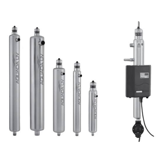
    1. Généralités et applications La désinfection de l’eau par la lumière ultraviolette (UV) est un procédé efficace, économique et particulièrement respectueux de l’environnement. La lumière UV détruit les micro-organismes pathogènes en quelques secondes sans laisser de résidus, de sous-produits nocifs et sans altérer l’odeur et le goût de l’eau. Les opérateurs n’ont pas à...
  • Page 44: Consignes Générales De Sécurité

    Consignes générales de sécurité RISQUE D’ÉLECTROCUTION! Attention – tension électrique dangereuse. Le non-respect de cette consi- gne peut entraîner des blessures graves. UNE PROTECTION OCULAIRE EST INDISPENSABLE! IMPORTANT! Conseils utiles ou autres informations. ATTENTION! Le rayonnement UV-C est dangereux pour les yeux et pour la peau ! N’utilisez les lampes UV que dans la chambre d’irradiation et seulement si des dispositifs de protection appropriés sont en place.
  • Page 45 • Vérifiez l’isolement électrique de l’appareil de désinfection avant d’effectuer les opérations suivantes: A. Préparation REMARQUE: Nous recommandons de confier les opérations de maintenance à des personnes qualifiées. B. Nettoyage C. Remplacement de la lampe UV • Avant toute opération d’entretien, dépressurisez l’appareil • N’utilisez pas la lampe UV à l’extérieur du réacteur UV Les lampes UV WEDECO ont été...
  • Page 46: Montage Et Installation

    2. Montage et installation Attention de respecter les normes et règles nationales pour le montage et l’installation. L’installation doit être effectuée uniquement par des techniciens qualifiés. Effectuez les vérifications suivantes avant l’installation: • Il ne faut pas dépasser une pression de service maximal de 1000 KPa •...
  • Page 47: Montage Du Réacteur

    2.1.1. Montage du Réacteur • Avant l’installation, vérifiez le type de réacteur. (Voir la plaquette signalétique). • Veillez à ce qu’il y ait assez d’espace libre au-dessus du réacteur (pour les dimen- sions, voir paragraphe 2.1.) pour installer la lampe UV et entretenir le système •...
  • Page 48: Installation De La Gaine De Quartz Et De La Lampe Uv

    2.1.2. Installation de la gaine de quartz et de la lampe UV Le réacteur est fourni avec une gaine de quartz. La tête de couleur noire qui doit recevoir la lampe UV a été serrée à un couple de 5 Nm dans notre usine. Avant la mise en service, vérifiez le serrage de tous les raccords vissés.
  • Page 49 Notice de montage La lampe UV doit égale- ment être nettoyée avant sa mise en place. Il faut Connecteur transparent l’introduire dans la tête par de lampe le dessus jusqu’à ce que les deux pattes transparentes Lampe UV s’enclenchent. Pièce de têtenoire Après la mise en place de la lampe UV, montez la fiche transparente sur la tête.
  • Page 50: Mise En Place Du Capteur Uv

    2.1.2.2. Mise en place du capteur UV Dans notre usine, le capteur UV a été mis en place (seulement pour le modèle Maxi- ma). Il reste à le visser sur le réacteur. Le serrage doit être effectué uniquement avec un outil léger. Un couple initial de 5 Nm est suffisant. Attention de ne pas dépasser ce couple, sinon vous risquez d’endommager le quartz du capteur.
  • Page 51: Système De Commande

    2.2. Système de commande Les variantes d’équipement suivantes peuvent être fournies: 1. Altima • Contrôle visuel de la lampe UV par le raccord de lampe transparent • Boîtier de commande facile à fixer (au mur ou sur le réacteur) 2. Proxima • Comme variante du système Altima •...
  • Page 52: Montage Du Boîtier De Commande

    2.2.1. Montage du boîtier de commande Le boîtier de commande peut être monté directement sur le réacteur à l’aide des colliers fournis. Sortez les colliers par l’ouverture du boîtier et fixez-les au réacteur. • Le boîtier de commande peut aussi être fixé au mur. Dans ce cas, percez deux trous (espacés de 134 mm) et mettez des chevilles et des vis.
  • Page 53: Mise En Place De La Lampe Uv

    2.2.3. Mise en place de la lampe UV • Déballez la lampe UV et essuyez-la avec un chiffon propre (ne la touchez pas avec les doigts) • Introduisez la lampe dans la tête jusqu’à l’enclenchement des pattes transparen- tes (en introduisant la lampe, pressez légèrement les pattes entre deux doigts; voir figure 1 page 52) 3.
  • Page 54: Système Sans Électrovanne

    • Appuyer sur le bouton de réinitialisation environ 10 secondes après avoir mis le système sous tension jusqu’à ce qu’un signal soit audible • Le système est en phase de préchauffage. Au bout de 5 minutes, l’électrovanne est sous tension et complètement ouverte. •...
  • Page 55: Contrôle D'étanchéité

    3.2. Contrôle d’étanchéité Après la mise en service, il faut vérifier l’étanchéité de tous les raccords vissés. ITT Water & Wastewater ne saurait être tenu responsable de dégâts occasionnés par l’eau. 4. Logiciel Les appareils Aquada (Proxima & Maxima) sont équipés d’un système de surveil- lance piloté...
  • Page 56: Messages D'alarme

    4.1. Messages d’alarme Les messages d’alarme suivants peuvent s’afficher en cours de fonctionne- ment: AL 1 » Panne de lampe UV AL 2 » Intensité UV inférieure à 55 % de la valeur de consigne AL 3 » Fin de vie de la lampe (jours d’utilisation = 0) AL 4 » Intensité comprise entre 55 % et 70 % de la valeur de consigne AL 5 »...
  • Page 57: Nouvelle Mise En Service Après Le Remplacement De La Lampe Uv

    » Installez une lampe neuve (utilisez exclusivement des pièces de rechange WEDECO d’origine) Alarme 4 • Vieillissement normal de la lampe UV (la désinfection est toujours assurée) • Nettoyez la lampe à bref délai • Le câblage de la lampe à filament est en face de la fenêtre du capteur »...
  • Page 58: Vue Éclatée

    5. Vue éclatée 1 » boîtier de commande 2 » réacteur 3 » gaine de quartz 4 » lampe UV 5 » pièce de tête 6 » joint torique (tête) 7 » connecteur transparent de lampe 8 » joint torique (gaine de quartz) 9 »...
  • Page 59: Liste Des Pièces De Rechange

    6. Liste des pièces de rechange Rev. Fabricant Description 760054 Boitier électrique AQUA 1 Altima 760055 Boitier électrique AQUA 2 & 4 Altima 760056 Boitier électrique AQUA 7 & 10 Altima 760057 Boitier électrique AQUA 1 Proxima 760058 Boitier électrique AQUA 2 & 4 Proxima 760059 Boitier électrique AQUA 7 &...
  • Page 61 WEDECO Aquada Installation and Maintenance Instructions Installations- und Wartungsanleitung Notice d’installation et de Maintenance Istruzioni di Installazione e Manutenzione...
  • Page 62 Contenuti Generale & Applicazioni Assemblaggio ed Installazione 2.1. Reattore 2.1.1. Assemblaggio del reattore 2.1.2. Installazione del tubo in quarzo e della lampada UV 2.1.2.1. Pulizia e sostituzione del tubo in quarzo 2.1.2.2. Installazione del sensore UV (solo per modello Maxima) 2.1.3. Connessioni al circuito idaulico esistente 2.2. Sistema di controllo 2.2.1.
  • Page 63 1. Generale & Applicazioni La disinfezione per mezzo della luce ultravioletta (UV) è un processo economico e parti- colarmente rispettoso dell’ambiente. La luce UV, infatti, uccide i microorganismi patogeni nel giro di poche secondi, senza lasciare alcun residuo, pericolosi sottoprodotti o sapori ed odori di alcun genere. Grazie a questo specifico meccanismo di azione, viene anche scongiurato per gli operatori il pericolo di esposizione e utilizzo di prodotti chimici pericolosi.
  • Page 64: Istruzioni Generali Di Sicurezza

    Istruzioni Generali di Sicurezza SHOCK ELETTRICO! Attenzione – scarica elettrica pericolosa. Il mancato rispetto di questa prescrizione potrebbe provocare seri infortuni alle persone. ASSICURARSI DI INDOSSARE PROTEZIONI PER GLI OCCHI! IMPORTANTE! Istruzioni per suggerimenti utili o informazioni di altro genere. ATTENZIONE! La radiazione UV-C è...
  • Page 65 • Assicurarsi che l’unità di disinfezione sia elettricamente isolata prima di: A. Effettuare riparazioni NOTA: WEDECO raccomanda di far effettuare le manutenzioni solo da personale qualificato. B. Effettuare la pulizia periodica C. Sostituire la lampada UV • L’unità UV deve essere depressurizzata prima della manutenzione • Non utilizzare la lampada UV al di fuori della camera di disinfezione Le lampade WEDECO UV sono progettate per funzionamento in continuo, al fine di assicurare le migliori performance di disin- fezione.
  • Page 66 2. Assemblaggio ed Installazione Assicurarsi che siano rispettati gli standard nazionali e le prescri- zioni per l’assemblaggio e l’installazione. L’installazione dovreb- be essere effettuata solo da tecnici qualificati. Verificare i seguenti punti prima dell’installazione: • Non superare la massima pressione di funzionamento 1000 K Pa (10 bar) •...
  • Page 67 2.1.1. Assemblaggio del reattore • Prima dell’installazione assicurarsi del tipo di reattore che si sta utilizzando. (l’informazione del tipo di reattore è reperibile sulla targhetta di identificazione) • Assicurarsi che ci sia spazio sufficiente al di sopra del reattore (per le dimensioni vedere la sezione 2.1.), altrimenti non sarà...
  • Page 68 2.1.2. Installazione del tubo in quarzo e della lampada UV Il reattore è fornito unitamente ad un tubo in quarzo già assemblato. L’apposito alloggiamento nero all’interno del quale deve essere inserita la lampada UV è stato già fissato con una coppia di 5 Nm. Prima del collaudo, verificare la tenuta idraulica di tutte le connessioni.
  • Page 69 Montaggio: introduzione Pulire anche la lampada UV prima di effettuare il nuovo assemblaggio. Inserire quindi Connessione traspa- la lampada UV dall’alto attra- rente lampada verso il pezzo capo lampada fino a che le due linguette Lampada UV di fissaggio trasparenti della presa di connessione non siano ben incastrate negli appositi alloggiamenti del...
  • Page 70 2.1.2.2. Fissaggio del sensore UV Il sensore UV viene già preventivamente fissato in fabbrica all’interno della camera di reazione (solo per modelli Maxima) per i collaudi interni. E’ quindi solo necessario svitarlo per normale manutenzione. La guarnizione di tenuta dovrebbe essere rimos- sa non a mano, ma solo usando un apposito arnese leggero.
  • Page 71: Sistema Di Controllo

    2.2. Sistema di controllo E’ possible fornire le seguenti varianti di equipaggiamento: 1. Altima • Controllo della lampada UV con funzione visiva attraverso la connessione traspa- rente • Unità di controllo che può facilmente essere applicata al reattore (da posizionarsi o sul reattore o a muro con apposite staffe) 2. Proxima •...
  • Page 72: Collegamenti Elettrici

    2.2.1. Assemblaggio dell’unità di controllo L’unità di controllo può essere fissata direttamente sul reattore o a muro tramite le apposite staffe fornite in equipaggiamento standard da WEDECO. Tirare le staffe attraverso le aper- ture dell’alloggiamento ed ag- ganciarle al reattore. •...
  • Page 73 2.2.3. Collegamento della lampada UV • Disimballare la lampada UV e pulirla con un panno pulito ed asciutto (non toccare la lampada con le dita) • Inserire la lampada nel pezzo capo lampada fino a che le linguette trasparenti di fissaggio della lampada vadano a fissarsi all’interno dell’alloggiamento del pezzo capo lampada (inserendo la lampada, premere dolcemente sulle linguette di fis- saggio con le dita così...
  • Page 74 • Tenere premuto il bottone Reset per circa 10 secondi dopo aver acceso l’unità, fino a udire un segnale acustico • Il sistema è ora nella fase di riscaldamento. Dopo 5 minuti la valvola solenoidale si accende aprendosi completamente. • Aprire la valvola di arresto completamente e lentamente. Aprire contemporanea- mente la valvola di sfiato per assicurarsi che defluisca anche l’aria residua presente nel reattore.
  • Page 75 3.2. Test di tenuta idraulica Verificare, dopo il collaudo, la tenuta idraulica di tutte le con- nessioni e/o giunzioni del sistema. ITT Water & Wastewater non si assume responsabilità per danni provocati da eccessiva pressione dell’acqua! 4. Software Le unità Aquada (Proxima & Maxima) sono equipaggiate con un’unità di monitorag- gio gestita da micro-controller.
  • Page 76: Messaggi Di Allarme

    4.1. Messaggi di allarme I seguenti messaggi di allarme possono essere visualizzati durante il normale funzionamento: AL 1 » Guasto lampada UV AL 2 » Intensità UV minore del 55 % del valore di settaggio AL 3 » Fine vita lampada (giorni rimasti = 0) AL 4 » Intensità UV tra il 55 % ed il 70 % del valore di settaggio AL 5 »...
  • Page 77 » Installare una nuova lampada UV (Usare solo pezzi di ricambio originali WEDECO) Alarm 4 • Normale invecchiamento lampada UV (disinfezione ancora in atto) • Potrebbe essere richiesta una procedura di pulizia • I filamenti elettrici della lampada si trovano di fronte al cristallo del sensore »...
  • Page 78: Diagramma Esploso

    5. Diagramma esploso 1 » unità di controllo 2 » reattore 3 » tubo in quarzo 4 » lampada UV 5 » pezzo capo lampada 6 » O-ring (capo lampada) 7 » connessione lampada 8 » O-ring (tubo in quarzo) 9 »...
  • Page 79: Elenco Parti Di Ricambio

    Elenco parti di ricambio ricambio Description 760056 Unità di controllo AQUA 7 & 10 Altima 760057 Unità di controllo AQUA 1 Proxima 760058 Unità di controllo AQUA 2 & 4 Proxima 760059 Unità di controllo AQUA 7 & 10 Proxima 760060 Unità...
  • Page 80 Un anno di garanzia (prorata) per la lampada UV ITT Water & Wastewater fornisce, per la lampade UV, un garanzia di anni uno (1) dalla data di acquisto (garanzia in accordo alla UV Lamp Warranty policy disponibile su richiesta).
  • Page 83 Notes/Notizen/Notes/Note: __________________________________________________________________________ __________________________________________________________________________ ___________________________________________________________________________ ___________________________________________________________________________ ___________________________________________________________________________ ___________________________________________________________________________ ___________________________________________________________________________ ___________________________________________________________________________ ___________________________________________________________________________ ___________________________________________________________________________ ___________________________________________________________________________ ___________________________________________________________________________ ___________________________________________________________________________ ___________________________________________________________________________ ___________________________________________________________________________ ___________________________________________________________________________ ___________________________________________________________________________ ___________________________________________________________________________ ___________________________________________________________________________ ___________________________________________________________________________ ___________________________________________________________________________ ___________________________________________________________________________ ___________________________________________________________________________ ___________________________________________________________________________ ___________________________________________________________________________ ___________________________________________________________________________ ___________________________________________________________________________...
  • Page 84 What can ITT Water & Wastewater do for you? Integrated solutions for fluid handling are offered by ITT Water & Wastewater as a world leader in transport and treatment of wastewater. We provide a complete range of water, wastewater and drainage pumps, equipment for monitoring and control, units for primary and secondary biological treatment, products for filtration, oxida- tion and disinfection, and related services.

Ce manuel est également adapté pour:

Wedeco aquada 2Wedeco aquada 4Wedeco aquada 7Wedeco aquada 10

Table des Matières