Publicité
Les langues disponibles
Les langues disponibles
Liens rapides
JS PRODUCTS | 6445 MONTESSOURI STREET, LAS VEGAS, NV 89113
(MAY18)
Part No. 41563
Copyright © 2018 D
D
WALT
and the D
WALT Logo are trademarks of the D
®
E
E
and are used under license. The yellow/black color scheme is a trademark for D
power tools & accessories.
Definitions: Safety Guidelines
The definitions below describe the level of severity for each signal word. Please
read the manual and pay attention to these symbols.
WARNING:
Indicates a potentially hazardous situation which, if not avoided, could
result in death or serious injury.
CAUTION:
Indicates a potentially hazardous situation which, if not avoided, may
result in minor or moderate injury.
(Used without word) Indicates a safety related message.
NOTICE:
Indicates a practice not related to personal injury which, if not avoided,
may result in property damage.
IF YOU HAVE ANY QUESTIONS OR COMMENTS ABOUT THIS OR ANY D
CALL US TOLL FREE AT: 1-844-377-8451
WARNING! Read and understand all instructions.
important safety and operating instructions.
before assembling this storage rack and save it for reference.
SAVE THESE INSTRUCTIONS
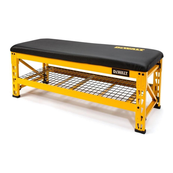
TECHNICAL SPECIFICATIONS
Technical Specifications
Seat Capacity
Shelf Capacity
Height
Width
Depth
Weight
GENERAL SAFETY
•
Keep work area clean and dry.
•
Use correct/recommended tools for the job.
•
Never leave unattended tools plugged in or running.
•
Never force a part into place.
•
Wear appropriate safety apparel for the job you are doing.
•
Wear safety glasses/goggles.
•
Keep small parts away from children. Never leave a small child unattended while assembling.
•
Always use common sense – your personal safety is your responsibility.
WARNING:
NEVER EXCEED THE FOLLOWING WEIGHT LIMITS
FOR THIS BENCH
•
Maximum load for bench seat: Up to 1,000 lb (454 kg) when weight is evenly distributed.
•
Maximum load for shelf: Up to 1,500 lb (680 kg) when weight is evenly distributed.
•
It is recommended that the heaviest load be placed on the bottom shelf.
DXSTFB048
Copyright © 2018, D
WALT
E
WALT.
E
WALT Industrial Tool Co., or an affiliate thereof
E
WALT TOOL,
E
This manual contains
Please read this manual carefully
1,000 lb (454 kg)
*when weight is evenly distributed
1,500 lb (680 kg)
*when weight is evenly distributed
19.75" (50.16 cm)
49.6" (126 cm)
15"
(21.77 cm)
48 lb
(21.77 kg)
Parts List
No. Description
1
Cushion Seat
2
Pre-Bolted Upright Assembly
3
Wire Deck
4
Crossbeam
5
Bench Top Support Strap (Black)
6
Recessed Shelf Support Strap (Yellow)
1
3
4
5
6
7
8
9
WALT
E
Tools Required for Bench Assembly: 4 mm Hex Key (included) OR 4 mm Hex Bit (included); Rubber Mallet
(not included), Flat-Head Screwdriver (not included).
BEFORE YOU BEGIN:
•
Read all instructions thoroughly.
•
Remove all components from the box, and lay them on the floor in an orderly fashion.
•
Wear eye protection.
•
Be cautious of sharp edges.
•
Keep this information for further reference.
Crossbeam Instructions (Fig. 1-3)
NOTE: It is recommended for one person to hold the pre-assembled upright frames in place while a second
person installs the crossbeams.
NOTE: Keep the bolt heads of the diagonal pieces of the uprights on the outside of the assembly (Fig. 1).
NOTE: The top crossbeams have 4 slots for their associated bench support straps, and the bottom crossbeams
have 3 slots for their associated support straps.
1. There is a set of locking tabs at both ends of every crossbeam. To begin assembly, take a crossbeam with 3
slots and insert the tabs into two of the holes on the lower portion of one upright frame. Engage the locking
tabs into the holes using a downward motion. The locking pin hole should be at the top. Make sure the end of
the crossbeam is flush against the upright frame. (Fig. 1-2)
2. Repeat for the opposite side of the upright frame. Tap the ends of the crossbeam closest to the upright frames
with a rubber mallet until fully seated. The crossbeam and locking tabs should easily slip into place. If they
do not, then recheck the alignment of the teardrop-shaped holes and tabs. Too much force may damage the
interlock between the crossbeam and upright frame.
3. Using the methods listed above, install the other crossbeam with 3 slots to the opposite side of the upright
frames, parallel to the first crossbeam you installed. Make sure both crossbeams are at the same level.
4. Continue by installing the top sets of crossbeams flush to the top of the upright frames (each top crossbeam
has 4 slots and one will have the D
the same level on both sides. (Fig. 2)
FIG. 1
LOCKING
PIN HOLE
*KEEP BOLT
HEADS OF
DIAGONAL
PIECE ON
OUTSIDE OF
ASSEMBLY
Safety Strap and Support Strap Instructions (Fig. 4-7)
NOTE: There are two (2) safety straps with weld nuts and three (3) recessed shelf support straps on the bottom
set of crossbeams.
NOTE: There are two (2) safety straps with weld nuts and four (4) bench top support straps on the top set
of crossbeams.
NOTE: Top and bottom crossbeams use different support straps.
1. Starting with the bottom set of crossbeams, place a safety strap with weld nut between the lower ridges of the
crossbeams where two sets of holes have been pre-drilled. Thread a safety strap bolt up through the bottom
of the pre-drilled holes and through the weld nuts, and fully tighten with the included hex key or drill bit. Repeat
for the second strap on this set of crossbeams, and continue for the last 3 straps. (Fig. 5)
Qty.
No. Description
1
7
Safety Strap With Weld Nut
2
8
Safety Strap Bolt
1
9
Locking Shelf Pin
4
10
4 mm Hex Key
4
11
4 mm Hex Bit
3
12
Locking Grid Clip
READ ALL INSTRUCTIONS
WALT badge on the far right). Make sure the crossbeams are attached at
E
FIG. 2
UPRIGHT
FRAME
Qty.
4
8
12
1
1
4
2
10
11
12
FIG. 3
Publicité

Sommaire des Matières pour DeWalt DXSTFB048
- Page 1 4 mm Hex Bit Recessed Shelf Support Strap (Yellow) Locking Grid Clip JS PRODUCTS | 6445 MONTESSOURI STREET, LAS VEGAS, NV 89113 (MAY18) Part No. 41563 DXSTFB048 Copyright © 2018, D WALT Copyright © 2018 D WALT. WALT and the D WALT Logo are trademarks of the D WALT Industrial Tool Co., or an affiliate thereof...
- Page 2 WALT WALT et le logo D WALT sont des marques de commerce de DEWALT Industrial Tool Co. ou d’une ® société affiliée à cette dernière et sont utilisés sous licence. L’agencement de couleurs jaune et noir est une marque de commerce des outlils électriques et accessorires D...
- Page 3 REMARQUE : Les traverses supérieure et inférieure sont surmontées de barres de renfort différentes. (MAY18) Part No. 41563 DXSTFB048 Copyright © 2018, D WALT 1. En commençant par le jeu de traverses du bas, placez une barre de sécurité avec l’écrou à souder entre les crêtes inférieures des traverses où...
- Page 4 Instrucciones para las barras de seguridad y las barras de apoyo (Fig. 4-7) ADVERTENCIA: NO EXCEDA LOS SIGUIENTES LÍMITES DE PESO AL NOTA: Hay dos (2) barras de seguridad con tuercas soldadas y tres (3) barras de apoyo empotradas en el USAR ESTA BANCO estante, en el conjunto inferior de las vigas transversales.